36
Tuning
For advanced drivers, there are further setup measures available for shock absorption.
Thus, in addition to the measures described above, you have the possibility of changing the absorption by ex-
changing the shock-absorber springs with more resistant/less resistant springs with progressive coiling. You can
also use a shock-absorber oil with lower/greater viscosity or piston plates with a different size/number of holes.
Adjusting the wheel tracking
Steering
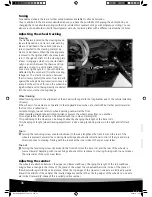
The track arms located on the steering knuck-
les are fastened on one track rod (a) each by
means of ball heads. These track rods are in
turn connected to the steering plate (b) by
means of ball heads. When the steering plate
is moved to the right and left, the wheels also
turn to the right and left. On the steering plate
a lever (c) engages, which is connected elasti-
cally on an axis between the chassis and top
deck via a spring to a second lever (d) posi-
tioned at a right angle to it. The second lever
is
deflected by the servo arm (f) via the steering
linkage (e). The elastic connection between
the two levers protects the servo from impacts
against the wheels during travel (servo saver) as
a result of the action of force on the wheels be-
ing absorbed and not being directly conducted
into the servo via the steering linkage.
Wheel tracking
Wheel tracking refers to the alignment of the wheels with regard to the longitudinal axis of the vehicle (direction
of travel).
If the wheels of one axle are not parallel to the longitudinal axis when at a standstill, but rather point inward at
the front, this is called toe-in.
Correspondingly, toe-out refers to wheels pointing outward at the front.
When travelling straight ahead, rolling resistance presses the wheels away from one another.
For compensation, the wheels can be adjusted with toe-in when standing still.
This positioning of the wheels can be brought about by changing the length of the track rods.
This changing of length (wheel tracking adjustment) is done using tensioning screws in the right and left track
rods.
Toe-in
Turning the tensioning screw counter-clockwise (to the rear) lengthens the track rod, and the rear of the
wheels is pressed outward. Toe-in during travel brings about better directional control of the tyre and more
direct response to steering. Driving with toe-in makes the inner sides of the tyres wear faster.
Toe-out
Turning the tensioning screw clockwise (to the front) shortens the track rod, and the rear of the wheels is
pressed inward. Adjusting with toe-out brings about a softer response to steering. Driving with toe-out makes
the outer sides of the tyres wear faster.
Adjusting the camber
The wheels are attached between the upper and lower wishbones. Changing the length of the top wishbone
brings about a change in the incline of the plane of the wheel. The wheel camber is the incline of the plane of
the wheel with regard to the vertical plane. When the top edges of the wheels on one axle are inclined inwards
(toward the middle of the vehicle), this is called negative camber. When the top edges of the wheels on one axle
are inclined outward (V-shaped), this is called positive camber.
a
a
b
c
d
e
f
MALI CARS MANUAL 2013 V3a .indd 36
30/09/13 16:43
Summary of Contents for desertfighter 2
Page 41: ...41 10 WATERPROOF Brushed Speedcontroller MALI CARS MANUAL 2013 V3a indd 41 30 09 13 16 43 ...
Page 42: ...42 MALI CARS MANUAL 2013 V3a indd 42 30 09 13 16 43 ...
Page 43: ...43 MALI CARS MANUAL 2013 V3a indd 43 30 09 13 16 43 ...
Page 44: ...44 11 WATERPROOF Brushless Speedcontroller MALI CARS MANUAL 2013 V3a indd 44 30 09 13 16 43 ...
Page 45: ...45 MALI CARS MANUAL 2013 V3a indd 45 30 09 13 16 43 ...
Page 46: ...46 MALI CARS MANUAL 2013 V3a indd 46 30 09 13 16 43 ...
Page 47: ...47 MALI CARS MANUAL 2013 V3a indd 47 30 09 13 16 43 ...
Page 48: ...48 MALI CARS MANUAL 2013 V3a indd 48 30 09 13 16 43 ...
Page 58: ...Notes MALI CARS MANUAL 2013 V3a indd 58 30 09 13 16 43 ...
Page 59: ...Notes MALI CARS MANUAL 2013 V3a indd 59 30 09 13 16 43 ...

