background image

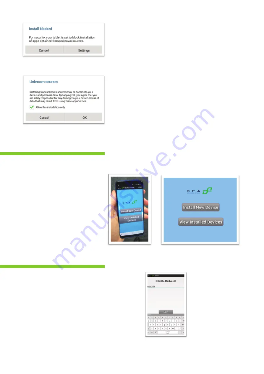
Fig. 2.1 Security message

Fig. 2.3 Linking the manhole cover

Fig. 2.4 Screenshot of linking process

Fig. 2.2 Security message

A mobile application is required to link the Visio Tamper 
device with the manhole ID, on installation. This is 
necessary to ensure that the alert data from the Visio 
Tamper device is associated with the correct manhole.

A URL link will be sent to the user, which can be used to 
download the Manhole Linking Application. The mobile 
application requires user permission to use the camera 
and to send data over the user’s network connection. 
When opening the file, the user must allow installation 
from “unknown sources” for this instance only, as per Fig. 
2.2.

To link the device to the manhole 
ID, click “Install New Device”:

Enter the manhole ID and click next
as per Figure 2.4

2. Device Linking

2

Summary of Contents for SqwidNET Visio Tamper

Page 1: ...SqwidNET Visio Tamper Device Manhole Tampering Solution Installation Guide ...

Page 2: ... Contents 1 Visio Tamper Device 2 Device Linking 3 Device Preperation 4 Device Installation Fibre reiforced Polymer Type 5 Device Intsallation Steel type 6 Materials Required for Installation 1 2 4 6 8 11 Page ...

Page 3: ...terproof device that sends an alert over the Sigfox network if the orientation of the device changes This makes it ideal for installation on the inside of manhole covers to monitor unauthorised access Fig 1 1 Visio Tamper device 1 Visio Tamper Device 1 ...

Page 4: ...s associated with the correct manhole A URL link will be sent to the user which can be used to download the Manhole Linking Application The mobile application requires user permission to use the camera and to send data over the user s network connection When opening the file the user must allow installation from unknown sources for this instance only as per Fig 2 2 To link the device to the manhol...

Page 5: ...ess Fig 2 7 Screenshot of linked devices Click confirm to link the device to the manhole The user has the option to view or hide device identities that have previously been linked to manhole identities Click Next to scan the device QR code on the reverse side of the Visio Tamper device 3 ...

Page 6: ...ly lift it up If necessary use a screwdriver to carefully pry open the enclosure once the screws have been removed Step 2 Plug in the power connector Instructions 1 Take care to maintain the original orientation of the back cover to the enclosure 2 Plug the 2 pin power plug into the board connector The green LED on the board will flash temporarily once power has been successfully connected 3 Devic...

Page 7: ... 7 Step 3 Close the device Instructions 1 Replace the back of the enclosure sliding the end furthest from the screws in first 2 Replace the screws and tighten until firm NB Take care not to over tighten the screws 5 ...

Page 8: ...mately 10mm from the manhole lip 2 Mark the position of the holes with a pencil or punch Step 2 Drilling Instructions 1 Mark a drill depth of 13mm on the drill bit 2mm diameter 2 Drill the hole vertically into the manhole cover taking care to stop at the marked depth 4 Device Installation Fibre reinforced Polymer Type 6 ...

Page 9: ...ews through the enclosure cavities and place the nylon spacers over the screws NB Failure to use the specified spacers may result in severe damage to the device 2 Place the device in position with the screws inserted in their respective holes 3 Tighten the screws until secure 7 ...

Page 10: ... cloth and solvent to clean the back of the Visio Tamper device 3 Allow solvent to dry approx 30 seconds 4 Use a brush to thinly apply the tape primer to the area of the manhole cover where the device will be installed 5 Use a brush to thinly apply the tape primer to the back of the Visio Tamper device 6 Allow the primer to dry completely 3 to 5 min 5 Device Installation Steel Type 8 ...

Page 11: ...Fig 5 5 below 3 Peel off the protective backing of the tape taking care not to touch the adhesive part 4 Apply recommended epoxy to centre area of the device taking care not to cover the tape 5 Place the device on the manhole cover in the position shown in Fig 5 7 below 6 Place firm pressure on the device for approx 20 seconds to ensure correct adhesion of the tape 9 ...

Page 12: ...Fig 5 5 Fig 5 6 Fig 5 7 Fig 5 8 10 ...

Page 13: ...Please see the Visio Tamper Installation Materials document for detailed information 6 Materials Required for Installation 11 ...

Reviews: