background image

www.d

fi

 .com

Chapter 2 Hardware Installation

18

Chapter 2

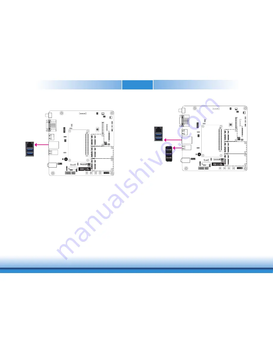
RJ45 LAN Port

The onboard RJ45 LAN port allows the system board to connect to a local area network by 

means of a network hub.

LAN 

1

ON

2
34

USB Ports

The USB device allows data exchange between your computer and a wide range of simultane-

ously accessible external Plug and Play peripherals. 

The system board is equipped with two onboard USB 3.0/2.0/1.1 ports (USB 0,1) and four 

onboard USB 2.0/1.2 ports (USB 2,3,4,5).

Driver Installation

You may need to install the proper drivers in your operating system to use the USB device. 

Refer to your operating system’s manual or documentation for more information.

Wake-On-USB Keyboard/Mouse

The Wake-On-USB Keyboard/Mouse function allows you to use a USB keyboard or USB mouse 

to wake up a system from the S3 (STR - Suspend To RAM) state. To use this function:

•  Jumper Setting

JP3 (USB 0,1) and JP2 (USB 2,3,4,5) must be set to “2-3 On: +5V_standby”. Refer to “USB 

Power Select” in this chapter for more information.

1

ON

2
34

USB 1

USB 0

USB 2.0

USB 2
USB 3
USB 4
USB 5

USB 3.0

Summary of Contents for COM100-B

Page 1: ...www dfi com Chapter 1 Introduction 1 COM100 B COM Express Carrier Board User s Manual A26130901...

Page 2: ...owners FCC and DOC Statement on Class B This equipment has been tested and found to comply with the limits for a Class B digital device pursuant to Part 15 of the FCC rules These limits are designed t...

Page 3: ...e Disable 12 LCD Inverter Power Select 13 BIOS Select 13 DC in Voltage Level 14 Backlight Brightness Power Select 14 LVDS eDP Signal Select 15 Rear Panel I O Ports 16 5V 19V DC in 16 Serial COM Ports...

Page 4: ...You must take extra care in han dling them to ensure against electrostatic build up 1 To prevent electrostatic build up leave the system board in its anti static bag until you are ready to install it...

Page 5: ...information listed above This may differ in accordance with the sales region or models in which it was sold For more information about the standard package in your region please contact your dealer o...

Page 6: ...ports Storage 1 SATA 3 0 port with data transfer rate up to 6Gb s Digital I O 8 bit Digital I O connector 4 bit GPI General Purpose Input 4 bit GPO General Purpose Output Rear Panel IO Ports 5V 19V D...

Page 7: ...Power Select JP14 1 Mini PCIe3 Power Select JP13 Mini PCIe3 Signal Select JP12 1 Line in Line out Mic in I2 C DC in Jack HDD Power 1 1 2 11 1 2 9 Smart Battery Charger SATA 1 Switch 5 1 ON 2 3 4 VCC5_...

Page 8: ...www dfi com Chapter 2 Hardware Installation 8 Chapter 2 Mechanical Drawing 0 00 10 16 154 94 159 84 0 00 6 35 21 23 54 83 73 83 94 89 124 83 151 76 163 65 22 86 44 14 91 14 34 21 110 21 157 48 163 65...

Page 9: ...r USB 2 3 4 5 are used to select the power of USB ports Select ing 5V_standby will allow you to use a USB keyboard to wake up the system USB Mode Select USB 0 1 JP3 USB 2 3 4 5 JP2 2 3 On 5V_standby 1...

Page 10: ...in the ROM BIOS please follow the steps below 1 Power off the system and unplug the power cord 2 Set JP6 pins 2 and 3 to On Wait for a few seconds and set JP6 back to its default setting pins 1 and 2...

Page 11: ...JP14 is used to select the power supplied with the LCD panel Important Before powering on the system make sure that the power settings of JP14 match the LCD panel s specification Selecting the incorre...

Page 12: ...sed to enable or disable the selection of Super I O VCC5_In Power Select 1 ON 2 3 4 JP4 1 2 On 5VSB default 3 4 On 5V 5 6 On NC 5 1 3 2 4 6 The JP4 is used to select the power of the COM Express conne...

Page 13: ...On 5V 3 1 2 3 1 2 The JP18 is used to select the power level of LCD inverter connector BIOS Select The JP20 is used to determine the BIOS boot device JP20 1 3 On 2 4 On Module SPI BIOS 1 ON 2 3 4 5 1...

Page 14: ...2 4 Off 5V 4 On 1 2 3 Off N C Backlight Brightness Power Select 3 1 2 3 1 2 2 3 On 3 3V 1 2 On 5V default The JP19 is used to select the power level of backlight brightness control 5V or 3 3V JP19 Im...

Page 15: ...d LVDS 1 2 On eDP 3 1 2 2 3 On LVDS default 3 1 2 Dimming Mode Select 3 1 2 3 1 2 2 3 On Voltage Mode 1 2 On PWM Mode default JP22 1 ON 2 3 4 The JP22 allows you to select the mode for the lightness c...

Page 16: ...ack 1 Mic in Center Subwoofer jack USB 3 0 0 1 COM 2 Line out COM 1 DisplayPort LAN DC in jack USB 2 0 2 3 4 5 Mic in Center Subwoofer Line in Surround This jack provides maximum of 120W power and is...

Page 17: ...can be used with modems serial printers remote display terminals and other se rial devices 1 ON 2 3 4 DisplayPort DisplayPort is a digital display interface used to connect a display device such as a...

Page 18: ...four onboard USB 2 0 1 2 ports USB 2 3 4 5 Driver Installation You may need to install the proper drivers in your operating system to use the USB device Refer to your operating system s manual or docu...

Page 19: ...system board is equipped with 3 audio jacks A jack is a one hole connecting interface for inserting a plug Line in Surround Jack Light Blue This jack is used to connect any audio devices such as Hi fi...

Page 20: ...w 2 1 19 Pin Pin Assignment Pin Pin Assignment 1 GND 2 12V 3 GPO3 4 12V 5 GPO2 6 GND 7 GPO1 8 5V 9 GPO0 10 5V 11 GPI3 12 GND 13 GPI2 14 5V_Standby 15 GPI1 16 5V_Standby 17 GPI0 18 GND 19 GND 1 ON 2 3...

Page 21: ...the pin functions of these connectors Jumper Settings Refer to the Jumper Settings section in this chapter for settings relevant to the LCD panel LVDS LCD Panel Connector LCD Inverter Power Connector...

Page 22: ...s legacy free systems It allows the integration of low bandwidth legacy I O com ponents within the system which are typically provided by a Super I O controller Furthermore it can be used to interface...

Page 23: ...et on the back side for broadband access via 3G networks Mini PCIe 3 supports both PCIe and mSATA signals and can be switched between these two with jumper JP12 PCI Express x1 Slot Install PCI Express...

Page 24: ...off the system PWR LED Power Standby LED When the system s power is on this LED will light When the system is in the S1 POS Power On Suspend state it will blink every second When the system is in the...

Page 25: ...8 J U 6 8J 768J66 AU 768J66 AU H 8 J 4 6 8J 5 676J6AK 6 8J53 K J 5 EU J 3 3 J57 U E 65 5 J U 65 5 J U J 5 E J 3 5 5J57 F 65 5 J 65 5 J 69 69 676J6HK 676J6 5 K 69 69 65 5 J U 65 5 J U J EU J EU 65 5 J...

Page 26: ...F 39 6J5 39 6J8 J E J E FA 39 6J5 U 39 6J8 U FH 39 6J5 39 6J8 J FU J FU F 39 6J5 U 39 6J8 U J F J F FE 39 6J5 39 6J8 FF 39 6J9 J 39 6J8AU 69 69 F 39 6J5AU 39 6J8A J U J U F 39 6J5A 39 6J8 3 J J J 4 4...

Page 27: ...e system to sleep or wake up mode 1 ON 2 3 4 Reset Lid Sleep Note The Sleep and Lid functions are supported only when your operating system supports ACPI Serial Interface Connector TX0 RX0 GND TX1 RX1...

Page 28: ...aster bus I2 C Connector 1 ON 2 3 4 1 2 5 6 3V3 Standby GND I2 C_Clock I2 C_DATA N C N C I2 C SMBus Connector The SMBus System Management Bus connector is used to connect the SMBus device It is a mult...

Page 29: ...he HDD power connector and the other end to your storage device The lithium ion battery powers the real time clock and CMOS memory It is an auxiliary source of power when the main power is shut off Sa...

Page 30: ...ttery Charger Connector 1 ON 2 3 4 Smart Battery Charger Connector 1 8 Pin Function 1 V 2 V 3 N C 4 SMB_CLK 5 SMB_DATA 6 N C 7 V GND 8 V GND Standby Power LED Standby Power LED This LED will lit red w...

Page 31: ...35 N C 16 eDP_AUX 36 Inverter PWR 17 GND 37 Inverter PWR 18 eDP Panel PWR 38 Inverter PWR 19 eDP Panel PWR 39 Inverter PWR 20 eDP Panel PWR 40 N C Note To switch output display signal between LVDS an...

Page 32: ...e perfor mance of the system board at https www dfi com product index 240 download Audio Driver To install the driver download COM100 B Audio Driver zip file at our website 2 Click Yes I want to resta...

Reviews: