58
4
Jumper Settings
VGA
Power-on Select
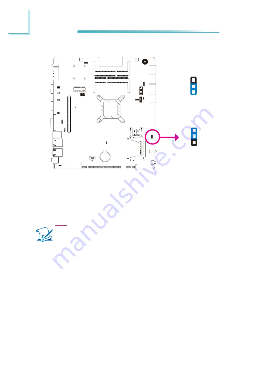
JP5 is used to select the method of powering on the system. If you want the
system to power-on whenever AC power comes in, set JP6 pins 2 and 3 to On. If
you want to use the power button, set pins 1 and 2 to On.
When using the JP5 “Power On” feature to power the system back on after a
power failure occurs, the system may not power on if the power lost is resumed
within 5 seconds (power
fl
icker).
Note:
In order to ensure that power is resumed after a power failure that re-
covers within a 5 second period, JP5 must be set to pins 2-3 and the
“PWRON After PWR-Fail” in CMOS is set to “On”.
1-2 On:
Power-on via
power button
(default)
2-3 On:
Power-on via
AC power
JP5
1
3
2
1
3
2
Summary of Contents for EC300 Series
Page 1: ...EC300 310 320 321 322 Series User s Manual A 221 M 2008 ...
Page 12: ...1 12 Introduction EC310 Series EC310 CR6881 EC310 CR6G60 EC310 CRA060 EC310 CR4866 ...
Page 14: ...1 14 Introduction EC321 322 CR4G65 EC320 321 322 CR4866 ...
Page 41: ...3 41 Installing Devices SATA power data connector SATA data connector SATA power connector ...
Page 117: ...6 117 Mounting Options 357 10 40 00 80 00 120 00 16 00 Ø8 50 R2 00 R2 50 ...
Page 159: ...159 8 Supported Software 3 Click Exit ...
Page 169: ...169 8 Supported Software 4 Click Finish ...
Page 182: ...182 8 Supported Software 4 After completing instal lation click Finish to exit setup ...


