background image

3

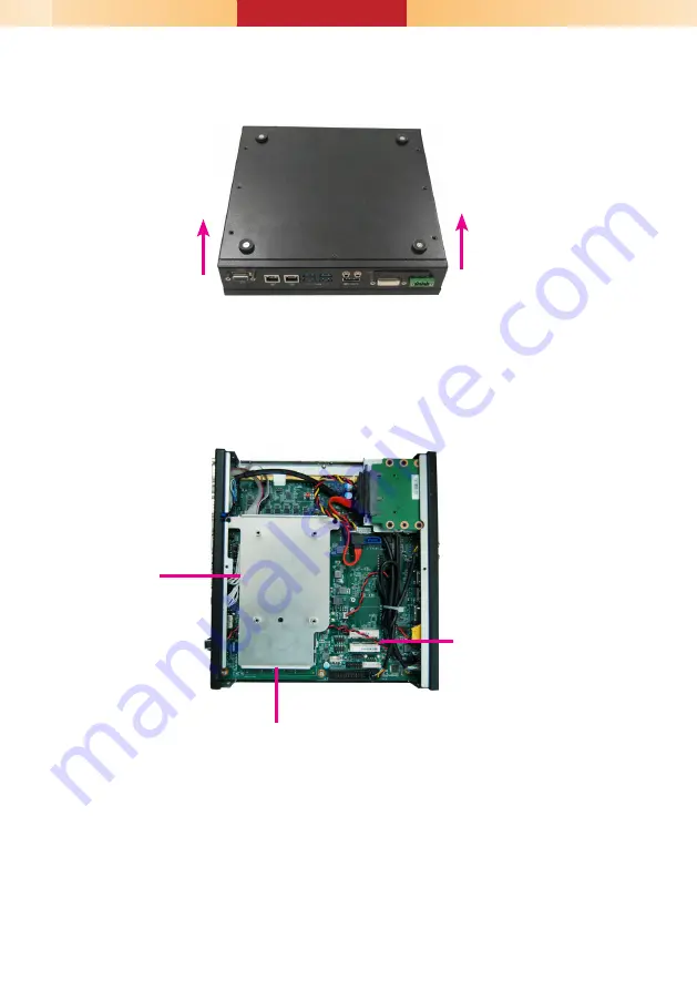
5.  The SODIMM sockets, Mini PCIe slot and SATA drive bay are accessible after removing the chassis 

cover.

4.  Lift the cover upward to open the system.

SODIMM socket

Mini PCIe slot

SATA drive bay

Summary of Contents for EC500-SD

Page 1: ...ote power on off DC in USB 3 0 DVI I DVI D Signal CFast LAN 1 LAN 2 VGA Line out HDMI Microphone Notes 1 Please gently press the power button to avoid possible damages 2 The HDMI is a DP HDMI combo po...

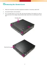
Page 2: ...ed to it have been powered off 2 Disconnect all power cords and cables 3 The 6 mounting screws on the left side right side and bottom of the system are used to secure the cover to the chassis Remove t...

Page 3: ...3 5 The SODIMM sockets Mini PCIe slot and SATA drive bay are accessible after removing the chassis cover 4 Lift the cover upward to open the system SODIMM socket Mini PCIe slot SATA drive bay...

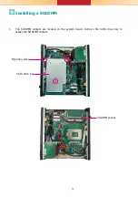
Page 4: ...4 Installing a SODIMM 1 The SODIMM sockets are located on the system board Remove the SATA drive bay to access the SODIMM sockets SODIMM socket SATA drive bay Mounting screw...

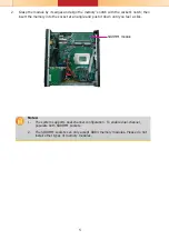
Page 5: ...emory into the socket at an angle and push it down until you feel a click Notes 1 The system supports dual channel configuration To enable dual channel populate both SODIMM sockets 2 The SODIMM socket...

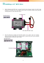
Page 6: ...n the HDD bracket with the mounting holes on the drive bay and use the provided mounting screws to secure the drive in place Mounting Screws Mounting hole 1 Before installing the SATA drive connect th...

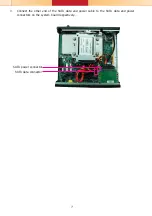
Page 7: ...7 3 Connect the other end of the SATA data and power cable to the SATA data and power connectors on the system board respectively SATA data connector SATA power connector...

Page 8: ...2 Gently insert the CFast card straight with the label on the CFast card facing up until you feel it lock into place Do not force the card into the slot if the card is not correctly inserted 3 Close t...

Page 9: ...will demonstrate the installation of a full size Mini PCIe card 1 Grasp the Mini PCIe card by its edges and align the notch in the connector of the Mini PCIe card with the notch in the connector on th...

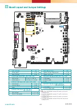
Page 10: ...JP1 Normal default 1 2 On Clear CMOS Data 2 3 On RS232 422 485 Select COM 1 JP5 JP12 COM 2 JP7 JP14 RS232 default 1 3 2 4 On RS422 Full Duplex RS485 3 5 4 6 On RS232 422 485 Select COM 1 JP6 COM 2 JP1...

Reviews: