www.dfi.com
8
Chapter 1 Introduction
Getting to Know the EC70A-SU
Chapter 1
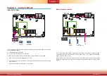
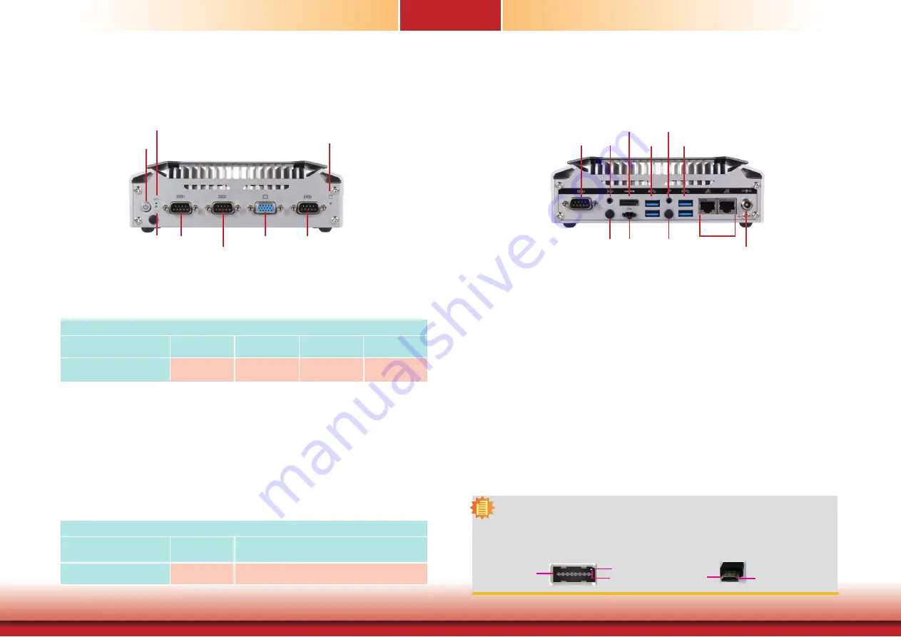
Front View
Power button with LED (Green)
Press to power on or power off the system.
Status LED (Blue)
Indicates system status.
Status LED
Suspend Mode
S0
S1
S3
S4, S5
LED Behavior
Always ON
Quick Blink
(cycle 1 sec)
Slow Blink
(cycle >1 sec)
Off
Reset Button
Press to reset the system.
COM Ports
Used to connect serial devices. COM 4 can be selected between an RS232 COM port or 8-bit
digital IO via jumper settings.
VGA
Used to connect the VGA connector of a monitor.
HDD LED (Blue)
Indicates the status of the hard drive.
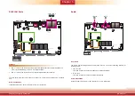
Rear View
COM Port
Used to connect serial devices.
Microphone/Line-out Ports
Used to connect audio devices such as microphones and speakers.
HDMI
Used to connect the HDMI connector of an LCD monitor.
USB 3.0 Ports
Used to connect USB 2.0/1.1 devices or USB 3.0 devices.
Switch
Used to connect a power switch for distant power on/off control.
Gigabit LAN Ports
Used to connect the system to a local area network.
DC-in
DC15~36V power input via a DC-in jack.
Antenna Holes
Used to connect a Wi-Fi module’s antenna.
HDD LED
HDD State
Disk access
activity
HDD present or HDD not present
LED Behavior
Blink
Off
COM 1
(RS232/RS422/RS485)
Power
(1)
(green)
Reset
HDD LED
(blue)
Status LED
(blue)
VGA COM 4
(RS232)/ 8-bit DIO
COM 2
(RS232/RS422/RS485)
HDMI
(2)
Antenna
hole
COM 3
(RS232)
LAN 2 LAN1
DC-in
USB 3.0
Line-out
Mic-in
Switch
USB 3.0
Antenna
hole
Notes:
1. Please gently press the power button to avoid possible damages.
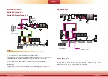
2. The HDMI is a DP/HDMI combo port but can only transmit HDMI signals (unless wired as a DP
port by request). Please plug in an HDMI cable with the right orientation and alignment to avoid
damage to the connector. You should feel resistance (due to a pin on the right) if the cable is not
inserted correctly.
Align this edge with the
left side of the connector
Angled-corner
(up)
Angled-corner
Aligning side
(left)
pin


