background image

www.dfi.com

1

Chapter 1 Introduction

ES520-HU

Desktop Box PC

User’s Manual

A40200546

Summary of Contents for ES520-HU

Page 1: ...www dfi com 1 Chapter 1 Introduction ES520 HU Desktop Box PC User s Manual A40200546...

Page 2: ...owners FCC and DOC Statement on Class A This equipment has been tested and found to comply with the limits for a Class A digital device pursuant to Part 15 of the FCC rules These limits are designed t...

Page 3: ...e Signal Select 17 Chapter 5 Ports and Connectors 18 Front Panel I O Ports 18 USB Ports 18 Rear Panel I O Ports 19 12V DC in 19 Graphics Interfaces 20 RJ45 LAN Ports 20 USB Ports 21 I O Connectors 22...

Page 4: ...igns of physical damage You must take extra care in han dling them to ensure against electrostatic build up 1 To prevent electrostatic build up leave the system board in its anti static bag until you...

Page 5: ...OT COVER THE OPENINGS Place the power cord in such a way that it will not be stepped on Do not place anything on top of the power cord Use a power cord that has been approved for use with the system a...

Page 6: ...res Model Name ES520 HU Processor 4th generation Intel CoreTM processors LAN 2 LAN ports COM 3 COM ports Display 2 HDMI USB 2 USB 2 0 ports at the front panel I O ports 4 USB 3 0 ports at the rear pan...

Page 7: ...GHz 2 9GHz 15W BGA 1168 packaging technology 22nm process technology Memory One 204 pin SODIMM socket Supports DDR3L 1333 1600MHz Supports up to 8GB system memory Supports single channel memory interf...

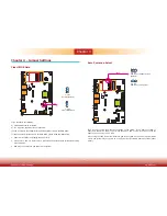
Page 8: ...system USB Ports Used to connect USB 2 0 1 1 devices Rear View COM LAN USB 3 0 DC in COM Ports Used to connect serial devices HDMI Port Used to connect a HDMI device USB Ports Used to connect USB 3 0...

Page 9: ...Dimensions Chassis Dimensions Motherboard Dimensions Chapter 1 166 00 50 00 157 30 DC 12V Front View Right View Left View Rear View 0 3 2 19 85 29 93 35 95 77 95 98 4 102 0 7 22 8 9 19 2 31 42 35 8 42...

Page 10: ...ory test the message Press DEL to run setup will appear on the screen Press the Delete key to enter the AMI BIOS setup utility Installing the Operating System Most operating system software are provid...

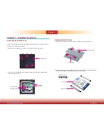
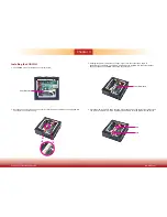
Page 11: ...tem Installing the SATA Drive 1 Fasten the 4 mounting screws that secure HDD brackets firmly to the system cover Mounting screw HDD bracket Mounting screw 4 2 Mini PCIe slots the SODIMM socket and the...

Page 12: ...er 3 Mounting screw SATA drive HDD bracket 3 Connect the SATA data cable and the SATA power cable to the connectors on the SATA drive 4 After completing steps above fasten the cover with 5 mounting sc...

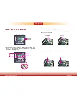
Page 13: ...nly 4 Press the memory module down until the clips at each end of the socket lock into position You will hear a distinctive click indicating the module is correctly locked into the socket SODIMM socke...

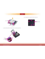
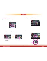
Page 14: ...The SIM card socket is located on the system board SIM card socket press backward release SIM card cover SIM card 3 Install a SIM card into the SIM card cover in position 4 Close the SIM card cover a...

Page 15: ...stalled into the slot without any gap between the Mini PCIe slot and the gold finger 4 Press the Mini PCIe card down and use the mounting screw provided to secure the half size or full size card on th...

Page 16: ...set JP1 back to its default setting pins 1 and 2 On 3 Now plug the power cord and power on the system 2 3 On Clear CMOS Data 1 2 On Normal default 3 1 2 3 1 2 JP1 Auto Power on Select 1 2 On Power on...

Page 17: ...f you are using the Wake On USB Keyboard Mouse function for 2 USB ports the 5V_standby power source of your power supply must support 1 5A For 3 or more USB ports the 5V_standby power source of your p...

Page 18: ...fer to chapter 7 for more information Important If you are using the Wake On USB Keyboard Mouse function for 2 USB ports the 5V_standby power source of your power supply must support 1 5A For 3 or mor...

Page 19: ...3 0 ports 1 Mic in 1 Line out 12V DC in DC in This jack provides maximum of 100W power and is considered a low power solution Connect a DC power cord to this jack We only provide 12V power adapter in...

Page 20: ...r to chapter 8 for more information RJ45 LAN Ports Features Intel I210 PCI Express Gigabit Ethernet controller Intel I218 with iAMT9 5 Gigabit Ethernet Phy The LAN ports allow the system board to conn...

Page 21: ...e BIOS Refer to chapter 7 for more information USB 2 0 1 2 10 9 VCC Data Data GND Key VCC Data Data GND N C Important If you are using the Wake On USB Keyboard Mouse function for 2 USB ports the 5V_st...

Page 22: ...I O Connector Pins Function 0 DIO7 1 DIO6 2 DIO5 3 DIO4 4 DIO3 5 DIO2 6 DIO1 7 DIO0 Front Audio Connector Digital I O Front Audio 1 Mic2 L Line2 R GND GND NC Key 2 10 Mic2 JD Line2 JD 9 Mic2 R Line2 L...

Page 23: ...485 2 1 9 DATA DATA GND NC NC NC NC NC NC 2 1 9 RXD DCD TXD DTR GND DSR RTS CTS RI Front Panel Connector HDD LED HDD LED This LED will light when the hard drive is being accessed RESET SW Reset Switch...

Page 24: ...rial ATA data cable to a SATA connector and the other end to your Serial ATA device BIOS Setting Configure the Serial ATA drives in the Advanced menu SATA Configuration submenu of the BIOS Refer to ch...

Page 25: ...the cooling fans Refer to chapter 7 for more information 1 3 Sense Power Ground CPU Fan System Fan 1 3 Sense Power Ground Expansion Slots Mini PCI Express Slots The Mini PCIe socket is used to instal...

Page 26: ...MBus Connector 1 2 5 6 GND 3 3V_standby SMBUS_Data SMBUS_CLK NC SMBUS_Alert SMBus Chassis Intrusion Connector The board supports the chassis intrusion detection function Connect the chassis intrusion...

Page 27: ...so will cause severe damage to the motherboard and components Standby Power LED Battery The lithium ion battery powers the real time clock and CMOS memory It is an auxiliary source of power when the m...

Page 28: ...1 The mounting holes are located at the bottom of the system 3 Mount the whole system on the wall by fastening the screws through the mounting holes Note The pictures in this document are used for il...

Page 29: ...www dfi com 29 Chapter 6 Mounting Options Chapter 6 5 00 8 50 16 00 80 00 182 60 5 00 8 50 16 00 80 00 182 60...

Page 30: ...u power up the system the BIOS message appears on the screen and the memory count begins After the memory test the message Press DEL to run setup will appear on the screen If the message disappears be...

Page 31: ...can Megatrends Inc Save Exit Chipset Version 2 15 1236 Copyright C 2012 American Megatrends Inc Select Screen Select Item Enter Select Change Opt F1 General Help F2 Previous Values F3 Optimized Defaul...

Page 32: ...Item Enter Select Change Opt F1 General Help F2 Previous Values F3 Optimized Defaults F4 Save Exit ESC Exit Trusted Computing This section configures settings relevant to Trusted Computing innovation...

Page 33: ...Technology When this field is set to Enabled the VMM can utilize the additional hardware capabili ties provided by Vanderpool Technology Select Screen Select Item Enter Select Change Opt F1 General He...

Page 34: ...F3 Optimized Defaults F4 Save Exit ESC Exit Intel R Rapid Start Technology This section is used to enable or disable the Intel Rapid Start Technology Aptio Setup Utility Copyright C 2012 American Meg...

Page 35: ...es the parameters of Active Management Technology Aptio Setup Utility Copyright C 2012 American Megatrends Inc Version 2 15 1236 Copyright C 2012 American Megatrends Inc Intel AMT Hide Un Configure ME...

Page 36: ...lect Change Opt F1 General Help F2 Previous Values F3 Optimized Defaults F4 Save Exit ESC Exit PCH FW Configuration This section only displays the parameters of Management Engine Technology Aptio Setu...

Page 37: ...3F8h IRQ 4 Auto Serial Port 1 Configuration to Serial Port 3 Configuration Sets the parameters of serial port 1 COM A to serial port 3 COM C Select Screen Select Item Enter Select Change Opt F1 Genera...

Page 38: ...ults F4 Save Exit ESC Exit Aptio Setup Utility Copyright C 2012 American Megatrends Inc Version 2 15 1236 Copyright C 2012 American Megatrends Inc Advanced Select Screen Select Item Enter Select Chang...

Page 39: ...Copyright C 2012 American Megatrends Inc Power Failure Control Power Loss State Advanced Power On Select Screen Select Item Enter Select Change Opt F1 General Help F2 Previous Values F3 Optimized Defa...

Page 40: ...ck This section is used to enable or disable UEFI network stack Enable Disable UEFI network stack Aptio Setup Utility Copyright C 2012 American Megatrends Inc Version 2 15 1236 Copyright C 2012 Americ...

Page 41: ...will not be created Aptio Setup Utility Copyright C 2012 American Megatrends Inc Version 2 15 1236 Copyright C 2012 American Megatrends Inc PCH IO Configuration System Agent SA Configuration Save Exi...

Page 42: ...et Select Screen Select Item Enter Select Change Opt F1 General Help F2 Previous Values F3 Optimized Defaults F4 Save Exit ESC Exit USB Configuration This field is used to configure the USB settings M...

Page 43: ...nds Inc Graphics Configuration IGFX VBIOS Version IGfx Frequency DVMT Pre Allocated LCD Control 2179 400 MHz 1024M Chipset Enter F1 F2 F3 F4 ESC Select Screen Select Item Select Change Opt General Hel...

Page 44: ...on will appear based on your selection VGA modes will be sup ported only on primary display Aptio Setup Utility Copyright C 2012 American Megatrends Inc Version 2 15 1236 Copyright C 2012 American Meg...

Page 45: ...e Quiet Boot Boot Option Priorities CSM Parameters Save Exit Chipset Advanced Security Main Boot 5 Off Disabled Select Screen Select Item Enter Select Change Opt F1 General Help F2 Previous Values F3...

Page 46: ...sion 2 15 1236 Copyright C 2012 American Megatrends Inc Save Changes and Reset Discard Changes and Reset Save Options Save Changes Discard Changes Restore Defaults Boot Override Launch EFI Shell from...

Page 47: ...has already been integrated into this system board Due to the safety concerns the BIOS SPI ROM chip cannot be removed from this system board and used on another system board of the same model 2 The B...

Page 48: ...to enhance the performance of the system board Insert the CD into a CD ROM drive The autorun screen Mainboard Utility CD will appear If after inserting the CD Autorun did not automatically start which...

Page 49: ...ipset can be recognized and configured properly in the system To install the utility click Intel Chipset Software Installation Utility on the main menu 2 Read the license agreement then click Yes 1 Se...

Page 50: ...n blank for 1 to 2 minutes while WinSAT is running before the Windows 7 Windows 8 desktop appears The blank screen period is the time Windows is testing the graphics performance We recommend that you...

Page 51: ...l the driver click Intel Management Engine Drivers 9 5 on the main menu 1 Setup is ready to install the driver Click Next 2 Read the license agreement then click Yes 3 Setup is currently installing th...

Page 52: ...e installation to take effect 1 Setup is now ready to install the driver Click Next 2 Follow the remainder of the steps on the screen clicking Next each time you finish a step Intel LAN Drivers To ins...

Page 53: ...e DFI Utility driver Click Next 2 Click I accept the terms in the license agreement then click Next DFI Utility DFI Utility provides information about the board Watchdog DIO and Backlight To access th...

Page 54: ...ick Install to begin the installation 5 After completing installa tion click Finish 3 Enter User name and Organization information then click Next The DFI Utility icon will appear on the desktop Doubl...

Page 55: ...www dfi com 55 Chapter 8 Supported Software Chapter 8 HW Health Set DIO WatchDog...

Page 56: ...8 Microsoft Framework 4 5 For Windows 7 To install the utility click Microsoft Framework 4 5 on the main menu 1 Read and accept the license agree ment Then click Installation 2 Setup is installing the...

Page 57: ...0 Driver on the main menu 2 Read the license agreement then click Yes 1 Setup is ready to install the driver Click Next 3 Go through the readme docu ment for more installation tips then click Next 4 S...

Page 58: ...perature management for the system protection To install the driver click Intel Dynamic Platform and Thermal Framework 7 1 on the main menu 1 Setup is now ready to install the utility Exit all program...

Page 59: ...license agreement then click Yes Intel Rapid Storage Technology The Intel Rapid Storage Technology is a utility that allows you to monitor the current status of the SATA drives It enables enhanced pe...

Page 60: ...tion to take effect Intel Rapid Start Technology The Intel Rapid Start Technology is a utility that allows your system to wake up and run faster To install the driver click Intel Rapid Start Technolog...

Page 61: ...click Next 6 Click Install Infineon TPM Driver and Tool optional To install the driver click Infineon TPM driver and tool option on the main menu 1 The setup program is preparing to install the driver...

Page 62: ...e Chapter 8 10 Click Yes to restart your system 7 TPM requires installing the Microsoft Visual C package prior to install ing the utility Click Install 8 The setup program is currently installing the...

Page 63: ...Adobe Acrobat Reader 9 3 To install the reader click Adobe Acrobat Reader 9 3 on the main menu 1 Click Next to install or click Change Destination Folder to select another folder 2 Click Install to be...

Page 64: ...2 In the Advanced menu select AMT Configuration 3 In the Advanced menu select Enable in the AMT field Aptio Setup Utility Copyright C 2012 American Megatrends Inc Version 2 15 1236 Copyright C 2012 A...

Page 65: ...press Enter Intel R Management Engine BIOS Extension v9 0 0 0029 Intel R ME v9 5 30 1808 Copyright C 2003 13 Intel Corporation All Rights Reserved MAIN MENU MEBx Login Intel R ME General Settings Inte...

Page 66: ...ME Password Move Highlight Enter Select Entry Esc Exit Intel R ME New Password 4 You will be asked to verify the password Enter the same new password in the space pro vided under Verify Password then...

Page 67: ...ve Highlight Enter Select Entry Esc Exit 7 Select Local FW Update then press Enter Select Enabled then press Enter Intel R Management Engine BIOS Extension v9 0 0 0029 Intel R ME v9 5 30 1808 Copyrigh...

Page 68: ...ion Mode Disabled Menu for FW Redirection Configuration INTEL R AMT CONFIGURATION 11 In the SOL IDER KVM menu select Username and Password then press Enter Select Disabled then press Enter Intel R Man...

Page 69: ...ture Selection Enabled Legacy Redirection Mode Disabled Disabled Enabled 15 In the SOL IDER KVM menu select Legacy Redirection Mode then press Enter Intel R Management Engine BIOS Extension v9 0 0 002...

Page 70: ...ol of KVM Opt in Policy then press Enter Intel R Management Engine BIOS Extension v9 0 0 0029 Intel R ME v9 5 30 1808 Copyright C 2003 13 Intel Corporation All Rights Reserved USER CONSENT User Opt in...

Page 71: ...d Move Highlight Enter Select Entry Esc Exit INTEL R ME NETWORK SETUP Intel R ME Network Name Settings TCP IP Settings 23 In the Intel R ME Network Name Settings menu select Host Name then press Enter...

Page 72: ..._ Domain Name _ Shared Dedicated FQDN Shared Dynamic DNS Update Disabled Disabled Enabled 27 Select Previous Menu until you return to the Intel R ME Network Setup menu Select TCP IP Settings then pre...

Page 73: ...d SOL IDER KVM User Consent Password Policy Anytime Network Setup Unconfigure Network Access Full Unprovision Remote Setup And Configuration Power Control 31 In the Intel R Remote Setup And Configurat...

Page 74: ...0 ME Wake in S3 S4 5 AC only Intel R AMT ON in Host Sleep States Mobile ON in S0 ME Wake in S3 S4 5 AC only Idle Timeout 65535 Move Highlight Enter Complete Entry Esc Discard Changes 35 In the Intel R...

Page 75: ...WDT Control WDT timer MOV DX 2EH MOV AL 07H Ready to Program Logical Device OUT DX AL MOV DX 2FH MOV AL 07H Select Logical Device 7 OUT DX AL MOV DX 2EH MOV AL F6H Select watchdog timer register OUT...

Page 76: ...which setting is correct either turn off the system and change the jumper or enter Setup and change the VIDEO selection FLOPPY DISK S fail 80 Unable to reset floppy subsystem FLOPPY DISK S fail 40 Fl...

Page 77: ...hat the video input cable is properly attached to the monitor and the system s display adapter 4 Adjust the brightness of the display by turning the monitor s brightness control knob The picture seems...

Page 78: ...ks by attaching it to a serial port that is working and configured correctly If the serial device does not work either the cable or the serial device has a problem If the serial device works the probl...

Reviews: