49
2
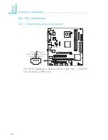
Hardware Installation
Pins
1
2
3
4
Function
+12V
+12V
Panel Backlight On/Off Control
+3.3V/+5V
Pins
5
6
7
8
Function
Panel Power
Panel Inverter Brightness Voltage Control
GND
GND
Pins
1
3
5
7
9
1 1
1 3
1 5
1 7
1 9
2 1
2 3
2 5
2 7
2 9
3 1
3 3
3 5
3 7
3 9
Function
GND
LV
LVDS_Out3-
GND
LV
LVDS_Out2-
GND
LV
LVDS_Out1-
GND
LV
LVDS_Out0-
GND
LV
LVDS_CLK1-
GND
COM3_DTR
COM3_RTS
COM3_RD
COM3_CTS
Pins
2
4
6
8
1 0
1 2
1 4
1 6
1 8
2 0
2 2
2 4
2 6
2 8
3 0
3 2
3 4
3 6
3 8
4 0
Function
GND
LV
LVDS_Out7-
GND
LV
LVDS_Out6-
GND
LV
LVDS_Out5-
GND
LV
LVDS_Out4-
GND
LV
LVDS_CLK2-
GND
COM3_TD
COM3_RI
COM3_DSR
COM3_DCD
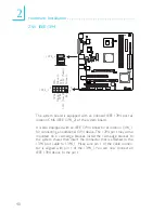
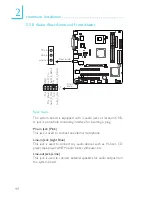
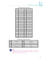
LVDS LCD Panel Connector
LCD/Inverter Power Connector
Note:
Jumper J5 is used to select the voltage supplied to the TTL
daughterboard. Pin 4 of the LCD/Inverter power connector will
depend on the voltage selected on J5.


