2
38
Hardware Installation
•
Line-in Jack (Light Blue - CN3B1)
This jack can be connected to the line-out jack of any exter-
nal audio devices such as Hi-fi set, CD player, AM/FM radio
tuner, synthesizer, etc. Connect a stereo cable from the line-
out jack of your external device to this line-in jack.
•
Mic-in Jack (Pink - CN3C1)
This jack is used to connect an external microphone.
The audio jacks at the rear panel will suppor t 6-channel audio only
when the audio utility is configured to support this function. The mic-
in at the rear will be disabled. Use the front audio’s mic-in jack.
Front Audio
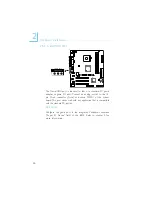
The front audio connector (J24) allows you to connect to the line-
out and mic-in jacks that are at the front panel of your system.
Using this connector will disable the rear audio’s line-out and mic-in
functions.
Remove the jumper caps from pins 5-6 and pins 9-10 of J24 prior
to connecting the front audio cable connector. Make sure pin 1 of
the cable connector is aligned with pin 1 of J24. If you are not using
this connector, make sure to replace the jumper caps back to their
original pin locations.
Driver Installation
Install the “Audio Drivers”. A 3D Audio Configuration program will
automatically be installed. This application program will allow you to
configure 2-channel, 4-channel and 6-channel audio modes as well as
configure the audio effects.
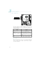
The front audio is disabled.
The rear audio is enabled.
The front audio is enabled.
The rear audio is disabled.
Pins 5-6 and 9-10 short
(default)
Pins 5-6 and 9-10 open


