Maintenance Manual DG-808C
Issued: May 2012
TN 800/41
4.8
4.7
Control surface seals and turbulators
Note:
To minimise the friction of the seals, the trailing edge of the seals should
be chamfered. Apply a fine grinding paper (e.g. 400 grit) between sealing and
control surface and move it up and down in spanwise direction to sand the
trailing edge of the sealing.
Caution:
Use only original materials see section 0. Otherwise the function of
the sealings is not guaranteed. Sealings which are too loose may cause control
surface flutter.
4.7.1
Wing upper surface
The sealing is installed in a groove at the trailing edge of the wing.
Mylar seal is glued into the groove with film tape at the leading edge of the
sealing. PVC tape is glued over the sealing to cover the gap between wing and
sealing. The leading edge of the PVC tape shall be 5 mm (1/5 in.) in front of this
gap.
Use seals not curved from root up to the outboard flaperon drive and curved
seals from the outboard flaperon drive up to the outboard end.
4.7.2
Wing lower surface turbulators
a)
Version with combi tape:
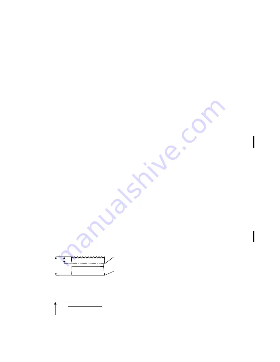
Sealing and turbulator are combined (combi sealing). The combi sealing is
already equipped with selfadhesive film tape. Prior to removing the old
combi sealing mark the position of the turbulator leading edge with a pencil
on the wing surface, otherwise see sketch distances a. The inboard combi
sealing is 7.0 m (22.97 ft.) long and 43 mm (1.7 in.) wide. The outboard part
is 1.45 m (4.76 ft.) long and 38 mm (1.5 in.) wide.
b)
Version with dimple tape:
Instead of combi tape a dimple tape may be installed as turbulator. The
sealing of the flaperon gap is done with the internal sealing according to
sect. 4.7.3. Operation without this sealing is not permitted. The leading edge
of the tape is located at distances b in front of the flaperon trailing edge.
y measured from fuselage centre line 1 in.=25.4 mm
. . . . .
hinge
line
trailing
edge
a
Position
y
mm
a
mm
b
mm
flaperon root
380 155
158
contour brake 4500 130
133
parting
7250 95
98
flaperon tip
8650 78
81
b
Summary of Contents for DG-800A
Page 3: ...Maintenance Manual DG 808C Issued June 2005 0 2 This page was intentionally left blank...
Page 113: ......
Page 114: ......
Page 115: ......
Page 116: ......
Page 117: ......
Page 118: ......
Page 119: ......
Page 122: ......
Page 123: ......
Page 124: ......
Page 125: ......
Page 126: ......
Page 127: ......
Page 128: ......
Page 129: ......
Page 130: ......
Page 131: ......
Page 132: ......
Page 133: ......
Page 134: ......
Page 135: ......
Page 136: ......
Page 137: ......
Page 138: ......
Page 139: ......
Page 140: ......
Page 141: ......
Page 142: ......
Page 143: ......
Page 144: ......
Page 145: ......
Page 147: ......
Page 158: ......


