background image

Page | 22  


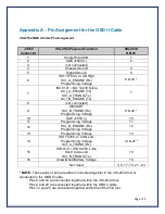
Appendix A – Pin Assignment for the OBD II Cable 


VSI-2534 OBD II Cable Pin Assignment 


J1962 

Connector 

VSI-2534 Purpose/Function 

VSI-2534 

DB 25 

Single Wire CAN 

SAE J1850 (+) 

(not connected) 


Chassis Ground 

Signal Ground 

ISO 15765-4 / CAN High 

SCI_A_ENGINE (Rx) 

Programming Voltage 

6 & 24 * 

ISO 9141 / ISO 14230 K-line 

SCI_A_ENGINE (Tx) 

SCI_A_TRANS (Tx) 

SCI_B_ENGINE (Tx) 

(not connected) 


GMUART 

SCI_B_TRANS (Rx) 

Programming Voltage 


9 & 20 * 

10 

SAE J1850 (-) 

10 

11 

Programming Voltage 

11 

12 

SCI_B_ENGINE (Rx) 

Programming Voltage 

12 

13 

Programming Voltage 

13 

14 

ISO 15765-4 / CAN Low 

Programming Voltage  

SCI_A_TRANS (Rx) 


14 & 25 * 

15 

ISO 9141 / ISO 14230 L-line 

Short to Ground 

SCI_B_TRANS (Tx) 

15 

16 

Unswitched Battery Voltage 

16 


Not Used 

3, 8, 17 -19, 21 - 23 


* NOTE: 

These pairs of pins are either connected together in the VSI-2534 tool or 

connected in the OBD II cable. 

Pins 6 and 24 are connected together within the VSI-2534 tool. 
Pins 9 and 20 are connected together within the OBD II cable. 
Pins 14 and 25 are connected together within the VSI-2534 tool. 


Summary of Contents for VSI-2534

Page 1: ...Manual Document Revision 3 6 Document Date August 2019 DG Technologies 33604 West Eight Mile Road Farmington Hills MI 48335 Phone 248 888 2000 Fax 248 888 9977 www dgtech com sales dgtech com techsup...

Page 2: ...e for back up purposes only I M P O R T A N T To ensure your success with this product it is essential that you read this document carefully before using the hardware Damage caused by misuse of the ha...

Page 3: ...1 First Time Hardware Connection to the PC 11 3 2 Typical Hardware Connection to the PC 12 3 3 Hardware Configuration Information 13 4 Software 14 4 1 VSI 2534 Validation Utility 14 4 2 DG Assist 14 4...

Page 4: ...ts 20 6 2 1 General Limitation and Risk Assignment 20 6 2 2 Exclusion of Incidental Consequential and Certain Other Damages 20 6 2 3 Limitation of Liability and Remedies 21 6 2 4 Right to Revise or Up...

Page 5: ...rent version of the J2534 API Version 04 04 and D PDU API Supports the following protocols CAN ISO 11898 J2284 Single Wire CAN ISO15765 ISO 9141 KWP2000 J1850 PWM Ford SCP J1850 VPWM both GM Class 2 a...

Page 6: ...d OBD II cable attached to the vehicle See 1 3 1 for more information on 12V DC usage WARNING The VSI 2534 SHOULD NOT be powered via the power jack AND the supplied OBD II cable SIMULTANEOUSLY Connect...

Page 7: ...nput An example of this scenario would be reflashing on the bench When powered via the supplied OBDII cable the Toggle Switch is not active 1 3 2 DB 25 This is the connector where the OBDII cable conn...

Page 8: ...VSI 2534 via the USB data link On Solid Red PC has initialized communication with VSI 2534 via the USB data link No bus activity On Alternating Red Green Activity on the PC VSI 2534 connection via US...

Page 9: ...4 EXE file on the CD and double click on it to start the software setup and then click Next 2 Exit all open Windows programs and click Next to continue 3 Choose Destination Location for the installati...

Page 10: ...Click Next to continue 5 Installing 6 Ensure that you do not have the VSI 2534 hardware connected to the PC s USB port Click OK to continue 7 Installation is complete Click Finish then click OK to reb...

Page 11: ...wer source Power adapter or powered from the OBD II cable Note do not power unit from multiple sources Power LED must be a solid Green Connect USB Cable to PC In some versions of Windows the final ste...

Page 12: ...ble to the PC that the software was installed on and note that the Power LED is a solid Green and the PC Connection LED is a solid RED Step 3 Connect the OBDII cable provided to the vehicle or using a...

Page 13: ...o not have any other application running that uses the J2534 library The Turn Logging ON checkbox enables the Configuration button The Configuration button enables the user to set Logging Type and Log...

Page 14: ...test versions of drivers for all your DPA DG Diagnostics and VSI 2534 products With this application running regularly and Automatic Firmware Update see DPA user manual turned on this will keep your D...

Page 15: ...and or virus protection software 4 6 2 DG Driver Update Initial Screen When the utility runs as a user logs on the following screen will appear in the lower right hand corner of the screen If you want...

Page 16: ...Drivers up to date No update necessary Red Drivers are outdated Update recommended Blue Drivers on your PC are newer than current version This usually indicates you are running a beta copy of the DPA...

Page 17: ...VSI or shut down your computer until installation is complete After the drivers have been downloaded to the Windows temp directory if you wish to save them for other machines they will be unzipped and...

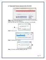
Page 18: ...4 Step 1 Go to Start All Programs DGTech VSI 2534 FirmwareUpdater NOTE Adaptor must be plugged in Select the drop down menu for Adapter and select VSI 2534 USB Step 2 Click on Yes Step 3 Updating the...

Page 19: ...elephone number DG Technologies Technical Support Phone 248 888 2000 Fax 248 888 9977 E mail techsupp dgtech com Web site www dgtech com Users not residing in the United States should contact your loc...

Page 20: ...m extent permitted by applicable law DG Technologies and its suppliers provide support services on an as is basis and disclaim all other warranties and conditions not specifically stated herein whethe...

Page 21: ...bligation to notify any individual or entity 6 2 5 Governance The user agrees to be governed by the laws of the State of Michigan USA and consents to the jurisdiction of the state court of Michigan in...

Page 22: ...Programming Voltage 9 20 10 SAE J1850 10 11 Programming Voltage 11 12 SCI_B_ENGINE Rx Programming Voltage 12 13 Programming Voltage 13 14 ISO 15765 4 CAN Low Programming Voltage SCI_A_TRANS Rx 14 25...

Page 23: ...Read Only Memory DG DG Technologies DPA DG Protocol Adapter DTC Diagnostic Trouble Codes ID Identification ISO International Standards Organization LED Light Emitting Diode OBD On Board Diagnostics OE...

Reviews: