Page | 7
1.3 Hardware overview
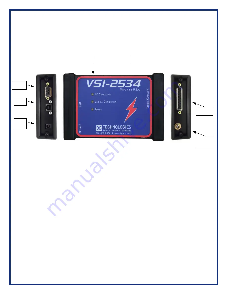
The following figures show the external features of the VSI-2534:
Figure 1: VSI-2534 Front & Side Views
1.3.1 Toggle Switch
The Toggle Switch can be used to simulate the vehicle ignition switch (on/off)
when the VSI-2534 is powered via a 12V DC input. An example of this scenario
would be reflashing on the bench. When powered via. the supplied OBDII cable,
the Toggle Switch is not active.
1.3.2 DB-25
This is the connector where the OBDII cable connects and powers the VSI-2534
from the vehicle connection.
1.3.3 DB-9
This is no longer in use.
1.3.4 USB
This is where the USB cable connects to the device to the PC.
1.3.5 12V DC
This is the external Power Connector.
Toggle
Switch
DB-25
DB-9
Status (3) Indicators
USB
12V
DC


