Page | 12
3.2 Typical Hardware Connection to the PC
Step 1:
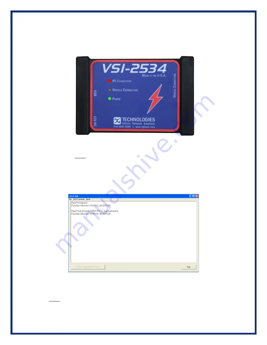
Connect the VSI-2534 to a power source (12V Power adapter
or
powered from
the OBD II cable). Note: Do not power unit from multiple sources. Power LED must be a
solid GREEN.
Step 2:
Connect the VSI-
2534’s USB cable to the PC that the software was installed on
and note that the Power LED is a solid Green and the PC Connection LED is a solid
RED.
Step 3:
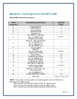
Connect the OBDII cable provided to the vehicle or using an application such as
the DG 2534 SDK (Software Development Kit), shown above, a user can open a link to
the hardware and connect with a protocol to a Vehicle or an Electronic Control Module
(ECU). Note: after this connection, the Vehicle Connection LED is a solid RED.


