background image

‐ 

24

 ‐ 

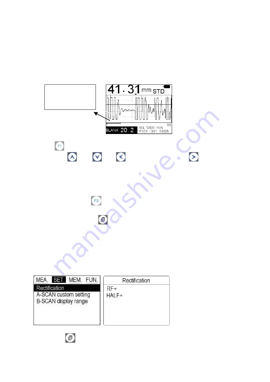
Blank


BLANK


is


used


in


T

E


mode.


Make


change


of


Blank


to


conceal


those


useless


echoes


that


influence


measuring


result.


When


making


changes,


the


red


line


at


the


left


bottom


conner


changes


accordingly.


User


could


take


it


as


for


reference


and


achieve


the


best


measuring


effect.


The


following


steps


outline


how


to


enable


and


adjust


the


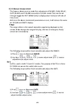
BLANK.


1)


Press


once


to


illuminate


BLANK.


2)


Use


keys


(+1),


(

1),


(

coarse


adjustment


),


(+


coarse


adjustment)to


adjust


value.


Saving


the


setting


Once


all


the


parameters


are


set,


there


is


two


ways


to


save


the


setting.


1)


The


user


can


Press


to


store


this


setting


into


the


current


location.


When


turn


on


the


gauge


next


time,


this


setting


will


be


displayed.


2)


Or


the


user


can


Press


to


store


this


setting


into


the


A

SCAN


CUSTOM


SETTING


for


further


use


while


measuring


the


same


workpiece.


8.2.7


Rectification


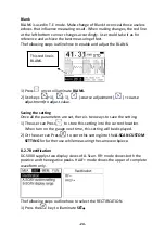
DC

5000


supplys


two


display


views


of


A

Scan.


RF+


mode


shows


both


the


positive


and


the


negative


peaks.


HALF+


mode


shows


the


upper


of


complete


waveform


only.


The


following


steps


outline


how


to


select


the


RECTIFICATION.


1)


Press


the


key


to


illuminate


SET


This


red


line


is


BLANK.
 

Summary of Contents for DC-5000

Page 1: ...UT Thickness Gauge DC 5000 Instruction Manual...

Page 2: ...2 3 Probe Calibration 20 8 2 4 Measurement rate 21 8 2 5 Auto measurement 21 8 2 6 Manual measurement 22 8 2 7 Rectification 24 8 2 8 A SCAN custom setting 25 8 2 9 B SCAN display range 26 8 3 MEM 26...

Page 3: ...probe recognition Automatic probe zero calibration Automatically locates the detection point if the measurement is out of the viewable display area Allow user to adjust the range of GAIN RANGE DELAY G...

Page 4: ...nge 1000m s 9999m s Measurement rate 2 s and 10 s in fast mode Average mode 2 to 9 times average measurement Limited setting With Low high indication and alarm Measuring Units mm inch Memory Memory of...

Page 5: ...Parameters field in highlight press this key to store the current set up parameters into the CUSTOM SETTING F1 Key Function 1 In A scan manual mode it is a toggle button mainly used to set up the par...

Page 6: ...y Function 1 It is used to navigate the menus and decrease values while setting the parameters Function 2 In A SCAN mode press this key to enter CUSTOM SETTING screen to open a setup that has been sav...

Page 7: ...own 4 Full waveform Display with green color means in testing with blue color means In frozen 5 Blank indicator The length of Red line changes with the BLANK number adjusted 6 Delay value indicator 7...

Page 8: ...Digital readout of thickness Display with white color means in testing with blue color means frozen 5 Gain value Can be adjusted from 10 50 6 Power life 7 Measuring unit millimeters or inches 8 Memory...

Page 9: ...Indicates where the current thickness reading is Located 5 Gain value Can be adjusted from 10 50 6 Velocity 7 Transducer model The transducer automatically recognizes and display 8 Power life 9 B sca...

Page 10: ...ement mode after Auto calibration Notice Please use the standard transducer offered Otherwise the unit does not work normally and displaying Error If users feel the thickness reading is incorrect duri...

Page 11: ...sound velocity of the workpiece which the thickness is known Please refer to 8 2 1 4 on page 4 Step Four Measurement The DC 5000 is now ready to measure There are four different measurement view opti...

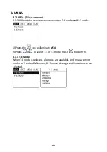
Page 12: ...T E mode and E E mode 1 Press the key to illuminate MEA 2 Press or to select T E or E E mode Press to confirm 8 1 1 T E Mode When T E mode is selected all probes are available And measurement modes o...

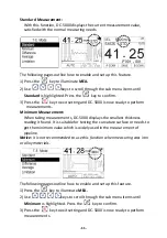
Page 13: ...inimum Measurement When taking measurements DC 5000 displays the smallest thickness reading it found It is suitable for testing the curvature surface or needs to get the minimum value which is widely...

Page 14: ...scroll through the sub menu items until Difference is highlighted Press the key to confirm The Display shows as follows 3 Press the or key to move the cursor 4 Press the or key to change the numbers a...

Page 15: ...he following pages outline how to enable and set up this feature 1 Press the key to illuminate MEA 2 Use keys to scroll through the sub menu items until Average is highlighted Press the key to confirm...

Page 16: ...and set up this feature 1 Press the key into MEA 2 Use keys to scroll through the sub menu items until Limitation is highlighted Press the key to confirm The display shows as follows 3 Use keys to set...

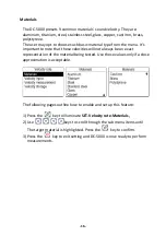
Page 17: ...s not set to the correct sound velocity all of the measurements the gauge makes will be erroneous by some fixed percentage If the name or sound velocity of the material to be measured is known the use...

Page 18: ...locities will not always be an exact representation of the material being tested Use these values only if a close approximation is acceptable The following pages outline how to enable and set up this...

Page 19: ...how to enter the velocity 1 Press the key to illuminate SET Velocity rate 2 Use keys to scroll through the sub menu items until VELOCITY INPUT is highlighted Press the key to confirm 3 Press the or ke...

Page 20: ...rial 3 The display should show a thickness reading probably incorrect 4 Having achieved a stable reading remove the transducer If the Displayed thickness changes from the value shown while the transdu...

Page 21: ...ate the target velocity Press to confim 4 Press to exit and DC 5000 is now ready to perform measurements 8 2 2 Resolution User can select the displayed resolution When 0 01mm or 0 001 inch be selected...

Page 22: ...red by some other means Or to use the build in standard test block 4MM comes with DC 5000 The following steps outline how to enable and set up this feature 1 Apply a drop of couplant on the transducer...

Page 23: ...nfirm 4 Press the key to exit setting and DC 5000 is now ready to perform measurements 8 2 5 Auto measurement This feature is recommended to measure some basic materials All parameters are preset acco...

Page 24: ...able range being displayed on the screen Make change the range of display shorten or enlarge it finally serve User conveniently The following steps outline how to enable and adjust the RANGE 1 Press o...

Page 25: ...resented in both the B SCAN and DIGITS views The following steps outline how to enable and adjust the GAIN 1 Press once to illuminate GAIN 2 Use keys 1 1 coarse adjustment coarse adjustment to adjust...

Page 26: ...Saving the setting Once all the parameters are set there is two ways to save the setting 1 The user can Press to store this setting into the current location When turn on the gauge next time this sett...

Page 27: ...so it eliminates error between two or more users during the setup and calibration process The following steps outline how to open store an A SCAN CUSTOM SETTING Opening a custom setting 1 Press the ke...

Page 28: ...items until B SCAN DISPLAY RANGE is highlighted Press the key to confirm 3 Press to move the cursor press or to change numbers Press to confirm 4 Press again to return to the measurement screen Then P...

Page 29: ...ement screen NOTE After taking every measurement press key to store this reading with a location number 8 3 2 Memory Read It is sometimes necessary to go back and view the stored readings The followin...

Page 30: ...eys to select YES or NO press key to confirm 8 3 5 Data Transfer The data can be transferred to PC using USB cable Then User could copy them into DOC TXT Or Excel for further analysis Procedure is as...

Page 31: ...er to adjust follwing functions 8 4 1 Swich off mode Auto shut down after 1 Min 3 Min 5 Min can be selectable 8 4 2 Languages The gauge provides muti languages for selection 8 4 3 Contrast User can ad...

Page 32: ...nit provides many measuring methods 1 Single point measuring method Use the probe to measure any point Of the workpiece to be measured and the displayed value is the thickness 2 Two point measuring me...

Page 33: ...appear at this moment User should replace the battery in time or it will affect the measuring accuracy The backlight cannot be switched on for a long time because it is a big consumer of electricity...

Page 34: ...0 075 Gold 3200 0 130 Ice 4000 0 160 Inconel 5700 0 220 Iron 5900 0 230 Iron cast 4600 0 180 Lead 2200 0 085 Magnesium 5800 0 230 Mercury 1400 0 057 Molybdenum 6300 0 250 Polyurethane 1900 0 0700 Pol...

Reviews: