background image

1


S

S

T

T

E

E

A

A

D

D

Y

Y

P

P

R

R

E

E

S

S


V

V

2

2

.

.

0

0


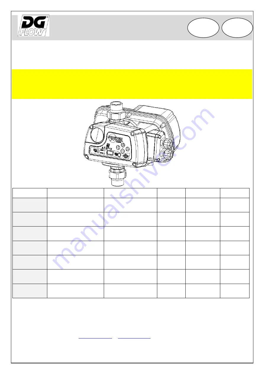
VARIATORE ELETTRONICO DI FREQUENZA (INVERTER) 

VARIABLE FREQUENCY DRIVE  (INVERTER) 

M

M

A

A

N

N

U

U

A

A

L

L

E

E


D

D

I

I


U

U

S

S

O

O


E

E


M

M

A

A

N

N

U

U

T

T

E

E

N

N

Z

Z

I

I

O

O

N

N

E

E


O

O

P

P

E

E

R

R

A

A

T

T

O

O

R

R

S

S


A

A

N

N

D

D


M

M

A

A

I

I

N

N

T

T

E

E

N

N

A

A

N

N

C

C

E

E


M

M

A

A

N

N

U

U

A

A

L

L


Model 

V in 

V out 

P (kW) 

P (HP) 

M/M 8.5 

1 ~   230V 

1 ~   230V 

8,5 

1,1 

1,5 

M/M 11 

1 ~   230V


1 ~   230V


11 1,5 2,0 

M/M 16 

1 ~   230V


1 ~   230V


16 2,2 3,0 

M/T 7 

1 ~   230V 

3 ~   230V 

1,1 

1,5 

M/T 12 

1 ~   230V 

3 ~   230V 

12 

2,2 

3,0 

T/T 6 

3 ~   400V


3 ~   400V


6 2,2 3,0 

T/T 8 

3 ~   400V


3 ~   400V


8 3,0 4,0 

 DGFLOW 

srl 


Tel. Via Emilia, 5 – 46030 Bigarello (Mantova) Italy 


+39 0376 340922 – fax +39 0376 249525 


info@dgflow.it

 – 

www.dgflow.it


10205407A.05 - 1604 

EN 

 IT 

Summary of Contents for STEADYPRES M/M 11

Page 1: ...MA AI IN NT TE EN NA AN NC CE E M MA AN NU UA AL L Model V in V out A P kW P HP M M 8 5 1 230V 1 230V 8 5 1 1 1 5 M M 11 1 230V 1 230V 11 1 5 2 0 M M 16 1 230V 1 230V 16 2 2 3 0 M T 7 1 230V 3 230V 7 1 1 1 5 M T 12 1 230V 3 230V 12 2 2 3 0 T T 6 3 400V 3 400V 6 2 2 3 0 T T 8 3 400V 3 400V 8 3 0 4 0 DGFLOW srl Tel Via Emilia 5 46030 Bigarello Mantova Italy 39 0376 340922 fax 39 0376 249525 info dgf...

Page 2: ...no decadere la garanzia sul prodotto In fase di prima istallazione ed in caso di manutenzione assicurarsi che Non ci sia tensione sulla rete di alimentazione elettrica La rete di alimentazione elettrica sia dotata di protezioni ed in particolare di interruttore differenziale ad alta sensibilità 30 mA in classe A per applicazioni domestiche ed in classe B per applicazioni industriali e di messa a t...

Page 3: ...rima messa in marcia 13 o Comunicazione tra inverter MASTER e SLAVE 13 o Allarmi 14 PARTE 2 MANUALE DI USO E MANUTENZIONE o Generalità 15 o Limiti di utilizzo 16 o Dati tecnici 16 o Dimensioni e pesi 17 o Codice di identificazione del prodotto 17 o Serbatoio autoclave 17 o Installazione per i collegamenti v ISTRUZIONI RAPIDE 18 o Autolimitazione per sovraccarico 18 o Prima messa in marcia 18 o Seg...

Page 4: ...rter in un locale o protetto dagli agenti esterni o areato esente da umidità eccessiva o polveri eccessive o il più vicino possibile alla pompa o in modo che non riceva vibrazioni nocive o sforzi meccanici dalle tubazioni collegate Descrizione della tastiera 1 Pulsante ACCENSIONE SPEGNIMENTO 2 LED rosso di messa in rete 3 LED verde di marcia 4 Display 5 Pulsante di SET 6 Pulsante di conferma Frecc...

Page 5: ...ND L N GND V W U LINE MOTOR N L Alimentazione inverter MONOFASE pompa MONOFASE M M tensione di alimentazione dell elettropompa 230 V monofase oppure 115 V monofase GND N L GND LINE MOTOR U W V Alimentazione inverter MONOFASE pompa TRIFASE M T tensione di alimentazione dell elettropompa 230 400 V trifase oppure 115 200 V trifase Collegare i morsetti dell inverter U V W A TRIANGOLO ai morsetti del m...

Page 6: ...vo di segnale ai morsetti 4 e 5 Nelle applicazioni con inverter in parallelo il cablaggio deve essere effettuato sull inverter MASTER COLLEGAMENTO DEL SEGNALE TRA GLI INVERTER RS485 10 9 8 7 6 5 4 3 2 1 10 9 8 7 6 5 4 3 2 1 10 9 8 7 6 5 4 3 2 1 collegare tra loro i morsetti 8 dei diversi inverter RS 485 i morsetti 9 dei diversi inverter RS 485 come mostrato a lato COLLEGAMENTO DEL SEGNALE DI ALLAR...

Page 7: ...le solo in modalità OFF La modalità TEST consente di avviare ed arrestare la pompa in manuale tasto START STOP e modificare la frequenza a passi di 1 Hz Consente inoltre di controllare i parametri di funzionamento del motore e dell inverter ATTENZIONE NEL FUNZIONAMENTO IN MANUALE ALCUNI DEI CONTROLLI AUTOMATICI SONO ESCLUSI E L OPERATORE DEVE EVITARE OGNI MANOVRA ERRATA ACCESSO AI PARAMETRI Per ac...

Page 8: ...T T TP INTERVALLO RIPERTENZE PER MARCIA A SECCO TF RITARDO ARRESTO PER FLUSSO NULLO RF RAPIDITA DI REAZIONE INVERTER FS FREQUENZA DI COMMUTAZIONE DEL MODULO US AVVIAMENTI ANTI BLOCCAGGIO EI SEGNALE IN INGRESSO EO SEGNALE IN USCITA AI FUNZIONE RICIRCOLO AT TEMPO ATTIVAZIONE RICIRCOLO W INDIRIZZO INVERTER V TENSIONE DI RETE Pd PRESSIONE iDRY FM MODULAZIONE FLAT SET F RIPRISTINA PARAMETRI DI FABBRICA...

Page 9: ...ore In presenza di basse tensioni di rete la corrente impostata deve prevedere un margine ad es 15 che compensi il basso voltaggio m u Default Min Max Step M M 8 5 A 8 5 1 8 5 0 1 M M 11 A 11 1 11 0 1 M M 16 A 16 1 16 0 1 M T 7 A 7 1 7 0 1 M T 12 A 12 1 12 0 1 T T 6 A 6 1 6 0 1 T T 8 A 8 1 8 0 1 RO SENSO DI ROTAZIONE DEL MOTORE solo modelli con uscita trifase PRESENTE SOLO PER USCITA TRIFASE Impos...

Page 10: ...1 PF 50 FATTORE DI POTENZA MINIMO solo modelli T T Imposta il valore minimo del fattore di potenza sotto il quale l inverter arresta la pompa per evitare la marcia a secco Per definire il valore minimo del fattore di potenza leggere il valore con la mandata completamente chiusa e sottrarre 3 punti come margine 0 50 0 50 0 99 0 01 TPF 0 RITARDO ARRESTO PER FATTORE DI POTENZA solo modelli T T Impost...

Page 11: ...relè si attiva se la pompa è in funzione EO 3 funzione ricircolo attiva il relè di uscita ad intervalli di tempo definiti dal parametro AI AI 60 FUNZIONE RICIRCOLO min Imposta gli intervalli di attivazione del segnale in uscita di tipo contatto pulito ed è attivo se EO è settato al valore 3 min 60 1 999 1 AT 10 TEMPO ATTIVAZIONE RICIRCOLO Imposta la durata di attivazione del segnale in uscita di t...

Page 12: ...lo coincide con la tensione di rete V PF 85 Power factor COSFI valore istantaneo del fattore di potenza solo modelli T T Tm 50 TEMPERATURA MODULO POTENZA Temperatura del modulo elettronico di potenza dell inverter C Ti 30 TEMPERATURA INTERNA INVERTER Temperatura dell ambiente interno inverter solo modelli T T C Tc 50 TEMPERATURA CONDENSATORI Temperatura dei condensatori solo modelli T T C In 0 STA...

Page 13: ...sualizzare i parametri di funzionamento con le frecce A fine TEST arrestare la pompa battendo il tasto START STOP ADESCAMENTO E PRIMA MESSA IN MARCIA Non avviare le pompe a secco Prima di avviare le pompe effettuare il riempimento di tutte le pompe Nei gruppi il riempimento avviene per pompa singola spegnendo tutte le altre pompe Quando la pompa è completamente riempita di acqua portarsi in modali...

Page 14: ...verter continua a funzionare l errore si azzera sotto i 60 C OVER TEMPERATURE BOX solo mod T T La temperatura interna dell inverter ha raggiunto gli 80 C l inverter arresta la pompa l errore si azzera sotto i 60 C e l inverter riprende a funzionare automaticamente HIGH TEMPERATURE MOD La temperatura del modulo dell inverter ha raggiunto il primo livello di allarme viene automaticamente limitata la...

Page 15: ...e elettrico estraibile 3 passacavo I O di potenza 4 coperchio scheda di potenza 5 giunto in 3 pezzi 6 targhetta dati tecnici 7 interruttore generale non presente nei modelli T T 8 fusibile non presente nei modelli T T 9 gruppo valvola di non ritorno 10 coperchio scheda espansione 11 box condensatori NOTA interruttore generale e fusibile sono presenti nelle sole versioni con alimentazione monofase ...

Page 16: ...variare della portata variazione della tensione di alimentazione ammessa 10 rispetto ai dati di targa DATI TECNICI tensione di alimentazione 230 10 Vac monofase modelli M M e M T ATTENZIONE IN PRESENZA DI VOLTAGGIO BASSO VALORE NOMINALE 10 SI POSSONO VERIFICARE SOVRACORRENTI IN AVVIAMENTO ED ALLA MASSIMA POTENZA 400 10 Vac trifase modelli T T tensione di uscita 230 Vac monofase modelli M M 230 Vac...

Page 17: ...rre al minimo l avviamento delle pompe è indispensabile in presenza di piccole perdite di impianto assorbe eventuali sovrapressioni provenienti dall impianto il volume minimo necessario in litri per modelli a membrana è indicativamente pari al 10 della portata massima della singola pompa espressa il l min esempio in applicazione standard Qmax 80 l min V 80 x 10 8 litri arrotondato per eccesso alla...

Page 18: ...vranno rispettare la normativa sulla compatibilità EMC in presenza di cavi lunghi tra inverter e motore es pompe sommerse si consiglia di valutare l applicazione di un filtro sinusoidale a protezione della pompa e dell inverter da picchi di tensione Collegamenti v ISTRUZIONI RAPIDE AUTOLIMITAZIONE PER SOVRACCARICO Se la corrente rilevata dall inverter Oppure la temperatura dei componenti inverter ...

Page 19: ...R STATUS STEADYPRES è in tensione ma la pompa non è in marcia STAND BY POWER STATUS STEADYPRES è in tensione e la pompa è in marcia POWER STATUS STEADYPRES è in tensione ma FUORI SERVIZIO oppure in TEST il ripristino è solo manuale POWER STATUS STEADYPRES è in allarme il ripristino è solo manuale MENU ISPEZIONE il menu INSP ispezione consente di visualizzare lo storico di funzionamento dell invert...

Page 20: ...a corretto che i cavi siano correttamente dimensionati CURRENT LIMIT Grave eccesso di assorbimento di corrente che eccede la capacità del modulo inverter controllare che l elettropompa non sia bloccata ridurre l accelerazione del motore parametro di fabbrica DRY RUNNING DRY RUNNING PF Mancanza di acqua in aspirazione pompa non adescata aspirazione ostruita rotazione inversa del motore verificare l...

Page 21: ...ONE DEL SENSORE DI PRESSIONE SCHEDA INTERFACCIA Togliere tensione all inverter ed attendere 2 minuti per la scarica dei condensatori Aprire il coperchio anteriore e procedere allo smontaggio del sensore di pressione e della scheda interfaccia come mostrato sotto Montare la nuova scheda interfaccia con sensore con procedimento inverso allo smontaggio Aprire il coperchio anteriore svitando le 4 viti...

Page 22: ...i ZERO verificare sul manometro ausiliario che la pressione di impianto sia nulla Premere il tasto SET TEST per confermare la pressione nulla SP 5 0 Avviare la pompa premendo il tasto START la pompa si avvia alla frequenza minima SP 5 0 Aumentare la frequenza della pompa premendo ripetutamente il tasto sino a raggiungere la pressione richiesta di 5 bar Se la pompa non raggiunge i 5 bar ridurre la ...

Page 23: ... v COLLEGAMENTO DEI SEGNALI chiudere il coperchio posteriore ESPLOSO RICAMBI N Descrizione Quantità KIT 1 Kit coperchio con tastiera 1 KIT 2 Kit sensore di pressione 1 KIT 3 Kit valvola di non ritorno sensore di flusso 1 KIT 4 Kit coperchio passacavi 1 KIT 5 Kit coperchio scheda di espansione 1 KIT 6 Kit box condensatori 1 7 GAS Kit giunto a 3 pezzi 1 GAS M 2 7 NPT Kit giunto a 3 pezzi 1 NPTS M 2 ...

Page 24: ...ttenersi alle norme e leggi in vigore nei paesi dove viene utilizzato il gruppo Non disperdere parti inquinanti nell ambiente DICHIARAZIONE DI CONFORMITA Dichiariamo sotto la nostra esclusiva responsabilità che il prodotto in oggetto è conforme alle seguenti direttive europee e disposizioni nazionali di attuazione 2006 95 CEE Direttiva Bassa Tensione 2002 95 CEE Sostanze pericolose nelle apparecch...

Page 25: ... spare parts tampering or improper use make the product warranty null and void During first installation or when carrying out maintenance make sure that the electric power supply network is not live The power supply network is equipped with protections and in particular of high sensitivity differential switch 30 mA in class A for domestic application class B for industrial applications and groundi...

Page 26: ...6 o Connection of inverter MASTER and SLAVE 36 o Alarms 37 PART 2 OPERATOR S AND MAINTENANCE MANUAL o General remarks 38 o Working limits 39 o Technical data 39 o Dimensions and weight 40 o Product identification code 40 o Surge tank 40 o Installation for connections see QUICK INSTALLATION GUIDE 41 o Self limiting overload 41 o Starting up 41 o Light signals 42 o Menu inspection INSP 42 o Troubles...

Page 27: ... the inverter in a place o protected from the elements o ventilated free from excessive humidity or excessive dust o as close as possible to the pump o make sure that does not receive harmful vibrations or mechanical stress from connected pipelines Control panel 1 START STOP button 2 Red LED power 3 Green LED status 4 Display 5 SET button 6 Confirm button 7 Scrolling UP DOWN RIGHT LEFT INSTALLATIO...

Page 28: ...t sinusoidal filter It aids smooth running of motors eliminating negative effect of voltage peaks GND L N GND V W U LINE MOTOR N L SINGLE PHASE IN line SINGLE PHASE OUT motor M M Pump supply voltage 230 V single phase or 115 V single phase GND N L GND LINE MOTOR U W V SINGLE PHASE IN line THREE PHASE OUT motor M T Pump supply voltage 230 400 V three phase Motor connection DELTA S V U W GND R LINE ...

Page 29: ...mps 4 e 5 In applications with parallel inverters the wiring must be carried out on the MASTER RS485 SIGNAL CONNECTION 10 9 8 7 6 5 4 3 2 1 10 9 8 7 6 5 4 3 2 1 10 9 8 7 6 5 4 3 2 1 Connect the terminals n 8 of the inverters in parallel RS 485 Connect the terminals n 9 of the inverters in parallel RS 485 as shown aside ALARM SIGNAL CONNECTION In applications with parallel inverters the wiring must...

Page 30: ... history etc TEST mode only in OFF mode TEST mode allows you to start and stop the pump in manual mode START STOP button and change the frequency in steps of 1 Hz It also allows to control the operating parameters of the motor and inverter WARNING DURING MANUAL OPERATION AUTOMATIC CONTROLS ARE EXCLUDED AND THE OPERATOR MUST AVOID ANY INCORRECT OPERATION ACCESS TO PARAMETERS BASIC ADV INSP TEST To ...

Page 31: ...AY FOR POWER FACTOR only T T models TP RESTART INTERVAL FOR DRY RUNNING TF STOP DELAY FOR NO FLOW RF INVERTER REACTIVITY FS MODULE SWITCHING FREQ US NO GRIP STARTUPS EI INPUT SIGNAL EO OUTPUT SIGNAL AI RECYCLE FUNCTION AT RECYCLE ACTIVATION TIME W INVERTER ADDRESS V MAINS POWER SUPPLY VOLTAGE Pd iDRY PRESSURE FM FLAT MODULATION SET F RESTORE FACTORY SETTINGS INSP WH OPERATING HOURS TH TOTAL OPERAT...

Page 32: ...rrent of the motor At low supply voltages the current set should leave a margin eg 15 to compensate for the low voltage m u Default Min Max Step M M 8 5 A 8 5 1 8 5 0 1 M M 11 A 11 1 11 0 1 M M 16 A 16 1 16 0 1 M T 7 A 7 1 7 0 1 M T 12 A 12 1 12 0 1 T T 6 A 6 1 6 0 1 T T 8 A 8 1 8 0 1 RO MOTOR DIRECTION OF ROTATION ONLY FOR THREE PHASE OUTPUT Set the direction of rotation of the three phase motor ...

Page 33: ...unning conditions CAUTION high values of the stop delay may damage the pump sec 10 1 100 1 PF 50 MINIMUM POWER FACTOR only T T models Sets the minimum value for the power factor below which the inverter stops the pump By setting the minimum power factor value read the value of the motor running with closed valves and deducting 0 03 to it 0 50 0 50 0 99 0 01 TPF 0 STOP DELAY FOR POWER FACTOR only T...

Page 34: ...ult EO 2 PUMP OPERATING OUTPUT there is at least one operating pump EO 3 recirculation activates the relay output time intervals defined by param AI AI 60 RECYCLE FUNCTION Sets the output activation interval clean contact type configured as recycle function Eo 3 min 60 1 999 1 AT 10 RECYCLE ACTIVATIO N TIME Sets the duration of the activation of the output signal clean contact type sec 10 1 999 1 ...

Page 35: ...SFI Shows the instantaneous value of the power factor only T T models Tm 50 POWER MODULE TEMPERATURE Displays the inverter s electronic module temperature C Ti 30 INVERTER BOX INTERNAL TEMP Displays the box internal Temperature only T T models C Tc 50 INVERTER BOX INTERNAL TEMP Displays the box internal Temperature only T T models C In 0 INPUT ACTIVATION STATUS Displays the input signal activation...

Page 36: ...the operating parameters by pressing the keys To stop the TEST press the A START STOP button PRIMING AND STARTING UP Do not run pumps dry Before starting the pump make the filling of all pumps In the pressure units the filling is for single pump by turning off all other pumps When the pump is completely filled with water bring in TEST mode manual operation and prime the pump by opening the dischar...

Page 37: ...drive continues to run the error is reset below 60 C OVER TEMP BOX only T T mod The temperature inside the inverter has reached 80 C the inverter stops the pump the error is reset below 60 C and the drive will restart automatically HIGH TEMPERATURE MOD The module temperature has reached the first alarm threshold the maximum working frequency is automatically limited but the drive continues to run ...

Page 38: ...type of system pressurization even existing Limits the peak currents during starts and operation energy saving Allows the selection of the power supply and output voltage PART LIST 1 control system 2 removable electric connector 3 I O power cable bushing 4 power board cover 5 three piece joint 6 tecnica data plate 7 master switch not present in T T models 8 fuse not present in T T models 9 non ret...

Page 39: ...O through the inverter to vary the flow rate TECHNICAL DATA main voltage supply 230 10 Vac single phase models M M e M T WARNING IN CASE OF LOW VOLTAGE NOMINAL VALUE 10 OVERCURRENTS CAN OCCUR DURING STARTING OR FULL LOAD OPERATION 400 10 Vac three phase models T T output voltage 230 Vac single phase models M M 230 Vac three phase models M T 400 Vac three phase models T T frequency 50 60 Hz enclosu...

Page 40: ...r under pressure to minimize the start up of the pumps it is essential in the presence of small system leakages absorbs overpressures from the system the minimum tank volume in liters for diaphragm models is approx equal to 10 of the maximum capacity of the single pump expressed in l min example in a standard application Qmax 80 l min V 80 x 10 8 liters rounded up to commercial size pre charge a 5...

Page 41: ...o comply with EMC standards In case of long cables between Inverter and pump motor evaluate the application of inverter output sinusoidal filter It aids smooth running of motors eliminating negative effect of voltage peaks For CONNECTIONS see QUICK INSTALLATION GUIDE SELF LIMITING OVERLOAD If the current detected by the inverter Or the temperature of the inverter Exceed the safety limits STEADYPRE...

Page 42: ... not detect power supply WARNING cannot guarantee the absence of power supply the electronic board may be faulty but under tension POWER STATUS STEADYPRES is live but the pump is not running STAND BY POWER STATUS STEADYPRES is live and the pump is running POWER STATUS STEADYPRES is live but out of serivce the re arm is only manual POWER STATUS STEADYPRES is in ALARM mode re arm is only manual INSP...

Page 43: ...orrect direction of rotation check the correct sizing of the wires CURRENT LIMIT Serious overcurrent absorption which inverter cannot cope with Make sure the motor pump is not blocked reduce the motor acceleration by means of the ACCELERATION parameter DRY RUNNING DRY RUNNING PF Lack of water at suction pump not primed suction blocked wrong direction of motor rotation Check correct suction conditi...

Page 44: ...ait 2 minutes capacitors discharge Open the front cover and disassembly the pressure sensor and the control board as shown below Install the new control board with pressure sensor in reverse order of removal Open the front cover by unscrewing the 4 screws Before removing the cover disconnect the ribbon cable of the display Disconnect the wire communication with the power board Remove FIRST the PRE...

Page 45: ...ssure SP 5 0 Start the pump by pressing START button the pump starts at the minimum frequency SP 5 0 Increase the frequency of the pump by pressing the button Until you reach the required pressure of 5 bar If the pump is not able to reach 5 0 bar reduce the required pressure by pressing the button e g to 4 bar SP 4 0 Check on the gauge that the pressure of the system is that required by the invert...

Page 46: ...Description Quantità KIT 1 Cover Kit with keyboard 1 KIT 2 Pressure sensor Kit 1 KIT 3 Non return valve flow sensor Kit 1 KIT 4 Cable bushing cover Kit 1 KIT 5 Expansion board cover Kit 1 KIT 6 Capacitor box Kit 1 7 GAS three piece joint 1 GAS M Kit 2 7 NPT three piece joint 1 NPT M Kit 2 8 Fuse only for single phase versions 1 10 RS485 expansion board alarms 1 KIT 1 KIT 2 KIT 6 KIT 4 KIT 3 KIT 5 ...

Page 47: ...ce in the countries where the unit is used Do not disperse pollutant parts in the environment DECLARATION OF CONFORMITY We declare under our own responsibility that the product in question is in compliance with the following European Directives and national implementation provisions 2006 95 CEE Low Voltage Directive 2002 95 CEE Dangerous substances in electronic appliances RoHS 2002 96 CEE e 2003 ...

Reviews: