background image

S O I L - D A Q ™


E Z - D A Q - S o f t   S O F T W A R E  


Operator’s Manual                                            EZ-DAQ™ version 1.4

                                                  15 

of

 25 

4.0 

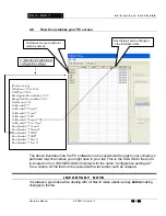
 How to customize your PC screen 


The above illustrates how the PC software can be customized to match your company’s 
particular machine names you might have in your lab. This is the EZ-DAQ.ini file and it 
is located in the C:\DGSI\EZ-DAQ\ directory with the name “configuration settings.ini”  
It is a simple .txt file that can be opened with a text editor such as notepad. 
 

I M P O R T A N T   N O T E  

It is always a good idea when dealing with .ini files to make a backup copy 

before

 making 

changes to the file. 


[Proface Setup] 
IPAddress=10.11.12.42 
UDPPort=1024 
ReadingStartMemAddress=100 
RangesStartMemAddress=200 
NumSensors=24 
ColHeader0="" 
ColHeader1="Travel" 
ColHeader2="Load" 
ColHeader3="PSI" 
ColHeader4="Grapes" 
ColHeader5="Test Time" 
RowHeader0="Consol" 
RowHeader1="Triaxial" 
RowHeader2="CBR" 
RowHeader3="LBR" 
RowHeader4="Test 5" 
RowHeader5="Test 6" 


C:\DGSI\EZ-DAQ\EZ-DAQ 
configuration settings 

Descriptions can be changed 
in the EZ-DAQ.ini file. 

Customize for your particular 
machine names. 

Summary of Contents for EZ-DAQ

Page 1: ...Q User Manual Version 1 4 Durham Geo Slope Indicator 2175 West Park Court Stone Mountain GA 30087 USA Phone 800 837 0864 or 1 770 465 7557 Fax 770 465 7447 e mail solutions durhamgeo com www DurhamGeo...

Page 2: ...o revise this publication and to make changes from time to time in its content without obligations to notify any person or organization of such revision or changes Information Record Model ___________...

Page 3: ...up 14 4 0 How to customize your PC screen 15 5 0 Displaying Your Results 16 CALIBRATION 18 1 0 Calibration of Sensors 18 2 0 Important Information 23 TROUBLESHOOTING 24 1 0 Troubleshooting 24 LIMITED...

Page 4: ...ured for a 200 mV input signal while Channel 8 can be configured for 4 20 mA signal These readings will be displayed on the screen and uploaded to the software All calibrations are held in the EZ DAQ...

Page 5: ...ation directory 4 0 Summary of Installation Instructions Ethernet Adaptor details on p 16 Plug the Belkin adaptor into a USB port on the host computer Windows will begin the installation process and a...

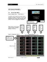
Page 6: ...Z DAQ PANEL 1 0 Screen Description Sensor Display Panel Home Screen A sensor is not a channel A sensor may be plugged into different channels Channels are numbered on the back of the EZ DAQ panel Sens...

Page 7: ...ons for that particular sensor only Note A single sensor may be set up for different test scenarios For Example you could have two sensors and run five tests with them Touch in CENTER of block to brin...

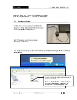
Page 8: ...Adaptor into the computer s USB port e NOTE Standard cat 5 ethernet cable not a cross over cable The computer will recognize the new hardware and will start loading software and drivers automatically...

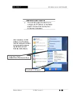
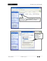
Page 9: ...s must be changed to enable communications between the EZ DAQ unit and EZ DAQ Soft software I M P O R T A N T N O T E The next few pages describe how to configure the IP address on the Belkin adaptor...

Page 10: ...R E Operator s Manual EZ DAQ version 1 4 10 of 25 c Left click on Internet Protocol TCP IP d Left click on Properties Right click on the newly installed USB device Left click on Properties BELKIN USB...

Page 11: ...then the EZ DAQ panel IP static address must also be changed The EZ DAQ box is set at 10 11 12 42 as a default Contact your IT dept or DGSI for instructions if address must be changed Type in the foll...

Page 12: ...0 EZ DAQ Soft Software Installation Insert CD into computer open the EZ DAQ software installation folder and double click Setup exe Setup will create a directory labeled DGSI EZ DAQ Computer must hav...

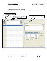
Page 13: ...3 of 25 The EZ DAQ Soft main screen will appear Notice Frame 6 is highlighted for values to be entered for test sampling intervals Area will be shaded out until a frame is selected See page 20 for det...

Page 14: ...nts User defined comments that will be on the top of the test printout Sampling Intervals Select the interval to change the sampling rate Intervals can be added with the insert button and removed with...

Page 15: ...with a text editor such as notepad I M P O R T A N T N O T E It is always a good idea when dealing with ini files to make a backup copy before making changes to the file Proface Setup IPAddress 10 11...

Page 16: ...DAQ Soft creates a file in the C DGSI EZ DAQ Data Directory To open the file simply click on It The computer will ask for a program to associate with Select Notepad from the list Note Headers will be...

Page 17: ...t S O F T W A R E Operator s Manual EZ DAQ version 1 4 17 of 25 From Text Data tab The above spread sheet file imported the data file using the Data tab and From Text button to use the delimited setti...

Page 18: ...NFIG button on the Sensor Configuration Block to enter the calibration configuration part of the screen software A window will open asking for a password The factory default password is 1234 It is rec...

Page 19: ...re labeled 1 8 These labels show the sensors numbers which you input in the the corresponding box First box INPUT CHL Touch the center of the numbered box Now a pop up box with a keypad will be displa...

Page 20: ...ed A D Counts will display a steady showing of an analog signal input from the sensor Sensor analog type mV V or mA A was coded into the unit before shipping to customer They do not interchange Call D...

Page 21: ...atile memory of the unit Maximize the sensors range then press the High End button on the touch screen This will load values from the sensor signals and store into non violatile memory of the unit Wit...

Page 22: ...ng for high signal input For example a 1 travel LVDT is actually a little longer maybe 1 023 Input the actual true travel the indicator has in the HIGH READ Or for a pressue transducer you would input...

Page 23: ...bove calibration steps have been provided for a yearly calibration check on the DGSI EZ DAQ touch screen Sensor types have been downloaded to the system by the factory before it shipped For example se...

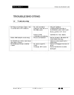
Page 24: ...ck IP address C DGSI EZ Daq Config ini and EZ DAQ panel must match Factory set for 10 11 12 42 Call DGSI for more details Belkin USB adaptor not working Drivers not installed Drivers located in EZ DAQ...

Page 25: ...der of the original warranty period whichever is greater IN NO EVENT SHALL DGSI BE LIABLE FOR CONSEQUENTIAL OR SPECIAL DAMAGES OR FOR INSTALLATION ADJUSTMENT LOST PROFITS OR OTHER COSTS WHICH MAY ARIS...

Reviews: