Manual DHMI 10.1
R01
USM_DHMI 10.1
Page 15/ 31
4.4
Commissioning
The device is delivered ready for operation. Proceed as described in the following paragraph during startup, and
also observe the safety instructions in Chapter 3.
Make sure that the voltage supply on the customer side is switched off first.
Mount the device in the intended location.
A +24 VDC power supply unit must be used for the power supply of the device.
The device must not be supplied with AC voltage.
Connect the negative line of the supply voltage to the negative pole of the HMI for the power supply.
Connect the positive line of the supply voltage to the positive pole of the single or double-pole connector of
the HMI for the voltage supply.
Switch on the supply voltage.
The device boots automatically.
5
Operation
Observe the safety instructions from chapter 3 and the start-up instructions from 4.4. To ensure safe operation,
the device may only be operated by trained personnel according to 3.2.
5.1
Interfaces
The device has various interfaces, which are listed and briefly explained below. It should be mentioned here that
the picoITX baseboard and a computer module from the DHSOM series are used in every DHMI device. The inter-
faces of the picoITX are routed to the outside and are therefore also available on the DHMI. In this paragraph the
interfaces are described briefly, detailed information can be found in the
the picoITX baseboard
on our website.
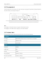
The interfaces relevant for DHMI are listed below:
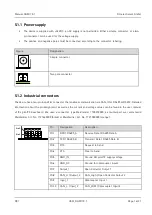
Voltage supply (X6 and X7) *
Industrial connectors with CAN, IO, RS485 and RS232 (X8)
USB (X10)
Ethernet (X4)
Status and Run LEDs
* Terminal designation on picoITX baseboard see User Manual picoITX

