Manual DHMI 10.1
R01
USM_DHMI 10.1
Page 16/ 31
5.1.1
Power supply
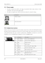
The device is supplied with +24 VDC, an AC supply is not permitted. Either a simple connector or a two-
pin connector can be used for the voltage supply.
The positive and negative poles must be connected according to the connector labeling.
Figure
Designation
Simple connector
Two pole connector
5.1.2
Industrial connectors
The device has a ten-pin industrial connector that enables communication via CAN, IO or RS485 or RS232. Detailed
information about the pin assignment as well as the current and voltage values can be found in the user manual
of the picoITX baseboard. We used a connector type Weidmüller 1728010000, as counterpart we recommend
Weidmüller Art. No. 1727660000 (black) or Weidmüller Art. No. 1727580000 (orange).
Pin
Designation
Description
Pin1
RXD | RS485_A
Receive Data | RS485 Data A
Pin2
TXD | RS485_B
Transmit Data | RS485 Data B
Pin3
RTS
Request to Send
Pin4
CTS
Clear to Send
Pin5
GND_IN
Ground DH picoITX supply voltage
Pin6
GND_OC
Ground for optocoupler inputs
Pin7
Output_1
Open Collector Output 1
Pin8
CAN_H | Output_2
CAN_High | Open Collector Output 2
Pin9
Input_1
Optocoupler Input 1
Pin10
CAN_L | Input_2
CAN_LOW | Optocoupler Input 2
+
-
+
+
-
-
Pin1
Pin2


