E-DWT-10000-AF OPERATION AND MAINTENANCE MANUAL
© 2008 DH Instruments, a Fluke Company
Page 100
•
Perform calibration of quartz reference pressure transducers (Q-RPTs), if necessary
(see Section 5.2.2)
5.5
E-DWT REPAIR
5.5.1
REMOVING RPM4-E-DWT FROM THE E-DWT
The E-DWT-10000-AF is an integrated assembly. The RPM4-E-DWT should not be removed
from the E-DWT unless it is necessary for RPM4-E-DWT and/or E-DWT repairs. The RPM4-E-DWT
should be calibrated in the E-DWT mounting system as the RPM4-E-DWT orientation may affect
its calibration.
To remove the RPM4-E-DWT A70M/A7M-AF from the E-DWT, proceed as follows:
Vent pressure from the RPM4-E-DWT.
Close the reservoir cap and reservoir vent valve. Do not overtighten cap, do not go CW
past CLOSE position.
Plug the test port and close the reservoir shutoff valve.
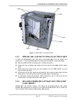
Place the E-DWT-10000-AF on it’s left side and remove two of the variable volume
handles to allow the E-DWT-10000-AF to lay flat on its side.
Remove the screws from the perimeter of the side panel using a 2 mm Allen head
wrench. Lift to remove panel.
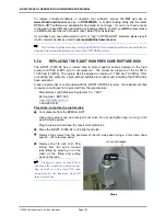
Remove the J1 ACC circular connector (LED assembly) and 12 VDC power cable from
the rear panel.
Using a 7 mm wrench, remove the nuts and lock washers from the front of the
RPM4-E-DWT side rack mount bracket. Then remove the nuts, washers, and lock
washers from both ends of the rear rack mount bracket.
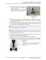
Using a 3 mm Allen head wrench, remove the M3 screws from the rear of the
RPM4-E-DWT rack mount bracket on both the right and left sides.
Do not remove the M3 screws from the lower right side of the rack mount kit as this will
detach the Variable Volume mounting bracket.
With the rear rack mount bracket loose, gently pivot it down and away from the
RPM4-E-DWT side rack mount bracket, and then remove the side rack mount bracket.
Remove the HIGH and LOW RPT pressure connections from the rear of the
RPM4-E-DWT with a 7/16 inch and ½ inch wrench. Do not remove the NPT thread
adaptors from the Q-RPT TEST(+) ports. Then gently pull back on the stainless steel
tubes to disengage from the adaptors.
The RPM4-E-DWT is now cleared for removal. Take care not to drag the RPM4-E-DWT
front panel across the two metal studs on the inside of the housing.
To reassemble, reverse the procedure. When reassembling the high pressure gland and
collar fittings, protect the conical tip from damage and be sure that the collar is fully threaded
on the nipple (left hand thread) before tightening the gland nut. Leak check all connections
after reassembly.

