3. OPERATION
Page 19
© 2008 DH Instruments, a Fluke Company
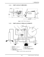
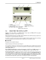
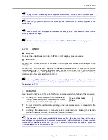
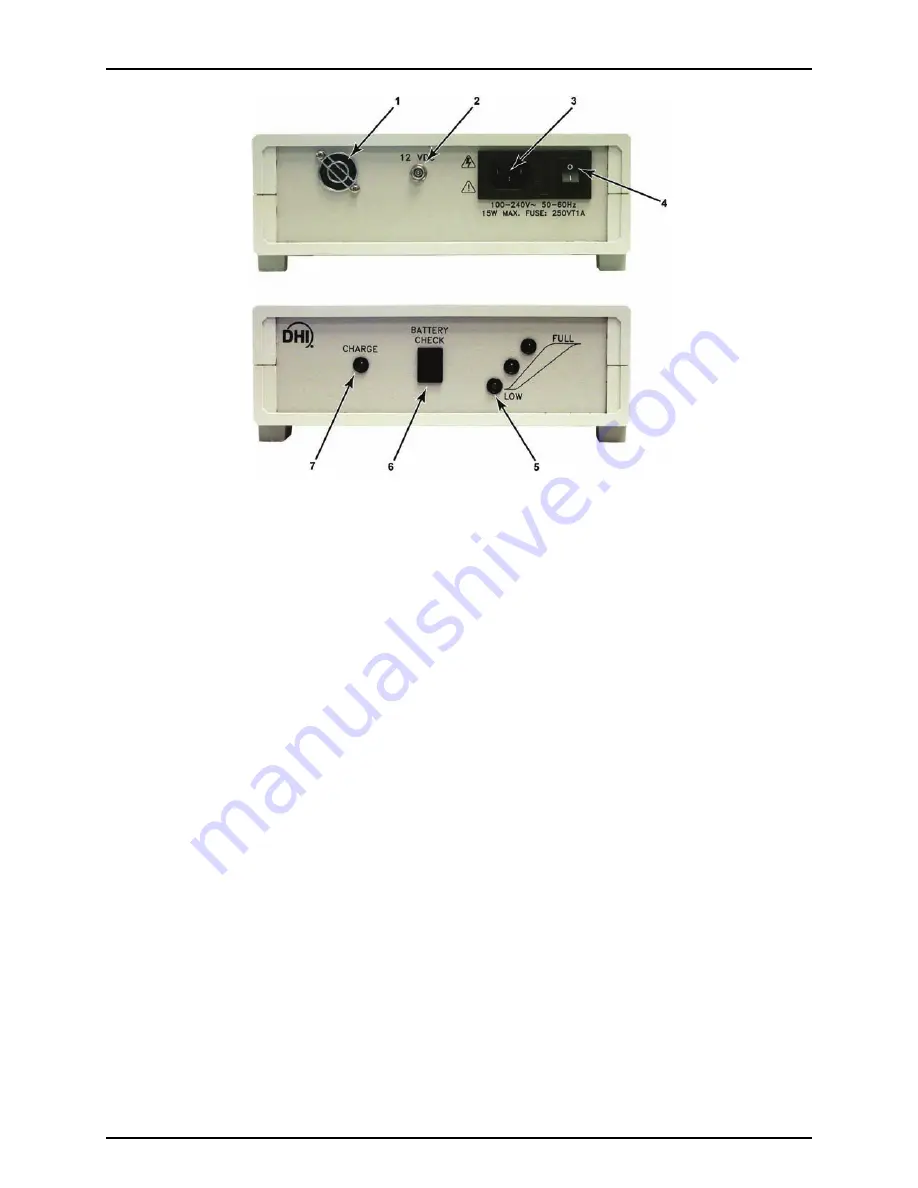
1. Cooling fan
2. 12VDC output connector (to E-DWT)
3. IEC power connection
4. ON/OFF switch (ON – battery connected to charger;
OFF - battery connected to 12 VDC output/E-DWT)
5. Charge level indicator
6. Charge level check switch
7. Battery charging indicator (green –
charging).
Figure 8.
Battery pack/charger
3.4
SELECTING THE HI OR LO Q-RPT
Selection of the active Q-RPT in the RPM4-E-DWT is made using the RPM4-E-DWT front panel’s
[RANGE]
key and E-DWT LO Q-RPT SHUT OFF valve.
When the Hi Q-RPT is active, the Lo Q-RPT must be isolated from the E-DWT’s pressure generation and
control system to avoid destroying it by overpressure.
The E-DWT’s Lo Q-RPT shut off valve and visual and audible indicators, assist the operator in performing
the correct operations to shut off and protect the Lo Q-RPT when the Hi Q-RPT is in use.
OPERATION
See Figure 10 for an E-DWT schematic.
Numerical references in this Section refer to Figure 9.
The Lo Q-RPT is connected to or shut off from the rest of the E-DWT by the Lo Q-RPT shut off valve that
is operated using the valve knob. The proper valve position for the Q-RPT selected is prompted by the
Valve Position LEDs
(7, 9).
The Lo Q-RPT shut off valve
(8) isolates and protects the Lo Q-RPT from the
TEST
port when it is
closed (knob fully CW) and opens the Lo Q-RPT to the
TEST
port when it is open (knob fully CCW).
The Valve Position LEDs
(7, 9) indicate the position in which the valve knob should be set based on the
current Q-RPT selection on the RPM4-E-DWT. If the Hi Q-RPT is selected, the
LO Q-RPT SHUT OFF
LED
(7) is lit indicating that the valve knob should be turned fully CW to close the valve, protecting the Lo Q-RPT
from high pressure. If the Lo Q-RPT is selected, the
LO Q-RPT ACTIVE
LED (9) is lit indicating that the valve
knob should be turned fully CCW to open the valve, connecting the Lo Q-RPT to the test pressure.


