background image


3.  OPERATION 


Page 37 

© 2008 DH Instruments, a Fluke Company 

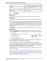
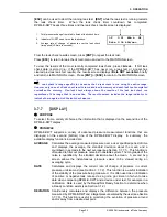
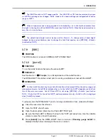
  Pressing [ENT] from the main run screen when the Deviation DISPLAY is active 

goes directly to the Target editing screen.  This allows the target value to be changed 

and without going through the DISPLAY menu. 


  If the pressure measurement unit or mode is changed while the Deviation 

DISPLAY is active the target value remains at the same numerical value.  It is  NOT 

converted. 


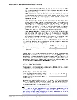
  To go to a DISPLAY other than Deviation, press [DISPLAY] and make a new 

DISPLAY choice (see Section 3.7.7).   


3.7.7.4


RPT 



  PURPOSE 

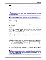
To activate the Q-RPT DISPLAY. 


 See 

Section 

3.7.7, 



 Principle. 




  OPERATION 


  For the sake of clarity, when describing the Q-RPT DISPLAY, the Q-RPT 

displayed on the top line of the display when the Q-RPT function is selected is 

referred to as the “active” Q-RPT.  The other Q-RPT to be displayed on the second 

(bottom) line of the RPM4-E-DWT display is referred to as the “inactive” Q-RPT.  It is 
“inactive” in the sense that all Q-RPT specific functions and settings such as UNIT 

still apply to the “active” Q-RPT.  To make changes to the “inactive” Q-RPT, for 

example to change its pressure measurement unit, it must be made the active Q-RPT 

by a range change (see Section 3.7.2).  


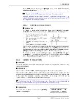
To activate the Q-RPT DISPLAY, press 

[DISPLAY]

<4RPT>

.  Operation returns 

to the MAIN RUN screen with the inactive Q-RPT displayed on the display’s 
bottom line.  The range of the inactive Q-RPT is always the default range, not an 
AutoRanged range (see Section 3.1.1). 

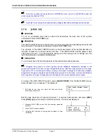
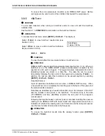
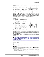
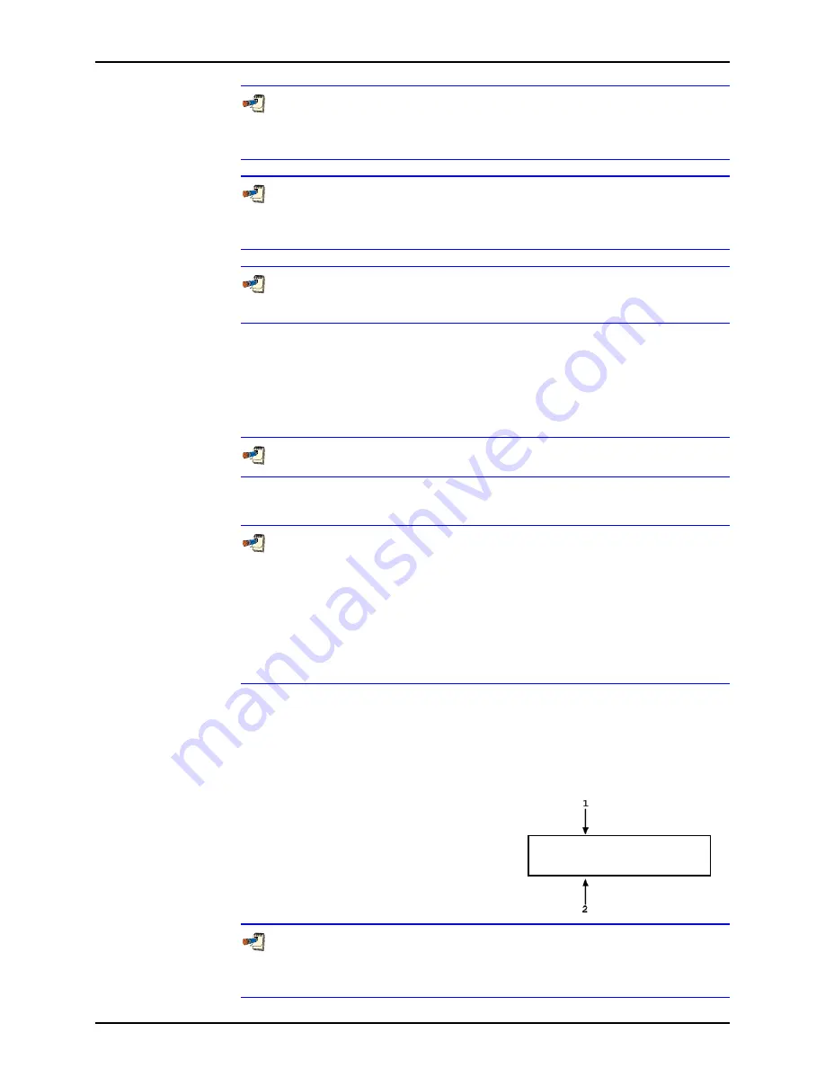
With the Q-RPT DISPLAY active the main run screen is: 

1. 

Active RPT display. 

2.  Inactive RPT display with Ready/Not Ready 

indicator on far left. 


 9911 psi g      zHi 

*0.7 psi g       zLo 


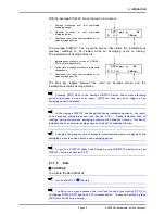
  When the Q-RPT display is active, executing a range change to a range on the 

inactive Q-RPT makes the inactive Q-RPT the active Q-RPT.  The DISPLAY defaults 

back to Rate ( Section 3.7.7.2). 

Summary of Contents for E-DWT-10000-AF

Page 1: ...2008 DH Instruments a Fluke Company E DWT 10000 AF Electronic Deadweight Tester Operation and Maintenance Manual NSN 6685 01 566 1341...

Page 2: ...y and quality of its published materials however no warranty expressed or implied is provided DH Instruments disclaims any responsibility or liability for any direct or indirect damages resulting from...

Page 3: ...F DIMENSIONS 7 1 3 5 E DWT 10000 AF HYDRAULIC SCHEMATIC 7 2 INSTALLATION 9 2 1 UNPACKING AND INSPECTION 9 2 1 1 REMOVING FROM PACKAGING 9 2 1 2 INSPECTING CONTENTS 9 2 2 SITE REQUIREMENTS 10 2 3 SETUP...

Page 4: ...8 HEAD 39 3 7 9 SDS 41 3 7 10 AUTOZ 41 3 7 11 ENT RUN AUTOTEST 42 3 7 11 1 AUTOTEST INITIALIZATION 43 3 7 11 2 TEST EXECUTION 44 3 8 SETUP 46 3 8 1 1RANGE 46 3 8 1 1 SAVING AN AUTORANGE RANGE 46 3 8...

Page 5: ...SING CALTOOL FOR Q RPTS SOFTWARE 97 5 3 6 EDITING AND VIEWING Q RPT CALIBRATION INFORMATION 97 5 3 7 Q RPT ADJUSTMENT WITHOUT CALTOOL FOR Q RPTS SOFTWARE 98 5 4 E DWT MAINTENANCE 99 5 4 1 E DWT OVERHA...

Page 6: ...E DWT 10000 AF OPERATION AND MAINTENANCE MANUAL 2008 DH Instruments a Fluke Company Page IV N NO OT TE ES S...

Page 7: ...iptions 73 Table 15 Calibration point sequence for A7M and A70M Q RPTs 97 Table 16 E DWT exterior illustrated parts breakdown see Figure 16 107 Table 17 E DWT internal illustrated parts breakdown see...

Page 8: ...00 AF front view 21 Figure 10 E DWT 10000 AF hydraulic schematic 21 Figure 11 MAIN RUN screen display fields 25 Figure 12 Keypad layout 26 Figure 13 RPM4 E DWT removal from E DWT 101 Figure 14 RPM4 E...

Page 9: ...r Section 5 provides maintenance and calibration information Section 6 is a quick troubleshooting guide Use it to troubleshoot unexpected E DWT behavior based on the symptom of that behavior For those...

Page 10: ...E DWT 10000 AF OPERATION AND MAINTENANCE MANUAL 2008 DH Instruments a Fluke Company Page VIII N NO OT TE ES S...

Page 11: ...DHI s RPM4 designated RPM4 E DWT A70M A7M AF RPM4 E DWT A70M A7M AF covers the range from 0 to 10 000 psi gauge pressure using two high precision quartz reference pressure transducers Q RPTs and an o...

Page 12: ...range 0 to 10 000 psi 70 MPa gauge pressure Operating medium Oil di ethyl hexyl sebacate Reservoir capacity 300 cc 18 in 3 Variable volume displacement 3 cc 0 18 in 3 Priming pump displacement 3 7 cc...

Page 13: ...erature stabilization recommended from cold power up Compensated Temperature Range 5 to 35 C Operating Temperature Range 18 to 28 C A7M Q RPT A70M Q RPT Maximum Range 1 000 psi 7 MPa 10 000 psi 70 MPa...

Page 14: ...sure small short term changes in atmospheric pressure to provide dynamic compensation of the Q RPT s atmospheric pressure offset in gauge pressure measurement mode see Section 3 9 1 Sensor Technology...

Page 15: ...n 12 VDC 6 Footswitch remote ENT connection footswitch not included Figure 2 E DWT 10000 AF rear view 1 3 2 RPM4 E DWT REFERENCE PRESSURE MONITOR VIEWS 1 3 2 1 FRONT PANEL 1 Pressure ready not ready i...

Page 16: ...t Lo Q RPT 9 ATM pressure port Hi Q RPT 10 Product label bottom of case Figure 4 RPM4 E DWT reference pressure monitor rear panel 1 3 3 BATTERY CHARGER PACK VIEWS 1 Cooling fan 2 12VDC output connecto...

Page 17: ...ATIC 1 TEST port 2 System pressure rupture disc 3 Reservoir 4 Reservoir vent valve 5 Priming pump 6 Test shut off and fine adjustment valve 7 Lo Q RPT shut off valve 8 Lo Q RPT pressure relief valve 9...

Page 18: ...E DWT 10000 AF OPERATION AND MAINTENANCE MANUAL 2008 DH Instruments a Fluke Company Page 8 N NO OT TE ES S...

Page 19: ...Receiving Department for appropriate action A new E DWT 10000 AF includes all items listed in Table 1 Table 1 E DWT 10000 AF packing list DESCRIPTION PART NO E DWT 10000 AF electronic deadweight teste...

Page 20: ...e E DWT is lit the red LED should NOT be ON If neither of the green LEDs lights check that the 12 pin circular connector on the rear panel of the RPM4 E DWT itself is properly connected to the J1 ACC...

Page 21: ...repeat the zeroing process If the display fails to zero properly the E DWT may need repair It is normal for RPM4 E DWT to indicate a value other than zero when vented when gauge mode is first entered...

Page 22: ...probably a leak in the E DWT and it may require service Rotate the variable volume handle CCW to reduce pressure to about 100 psi 700 kPa and open the reservoir shut off valve Put the Lo Q RPT shut of...

Page 23: ...followed carefully it is not necessary to empty the reservoir prior to shipment IMPORTANT Close the reservoir cover fully by rotating it CW until snug with reservoir vent valve aligned with CLOSE pos...

Page 24: ...E DWT 10000 AF OPERATION AND MAINTENANCE MANUAL 2008 DH Instruments a Fluke Company Page 14 N NO OT TE ES S...

Page 25: ...nges available on the RPM4 E DWT are accessed using RANGE see Section 3 7 2 and or created using AutoRange see Section 3 7 5 An RPM4 E DWT range is identified by a range screen showing the Q RPT used...

Page 26: ...has been achieved Ready is indicated when the current stability rate of change of pressure is less than the stability limit The user can set the stability limit see Section 3 8 3 or the stability limi...

Page 27: ...rvoir shut off valve The RPM4 E DWT indication may not be zero if the DUT reference height is different from the E DWT reference height 3 2 TEST PORT CONNECTION A single high pressure TEST port is pro...

Page 28: ...hours for the battery to charge fully When the battery charger power switch is in the ON position the battery is connected to the charger not the 12VDC output When the battery charger switch is in the...

Page 29: ...i Q RPT is in use OPERATION See Figure 10 for an E DWT schematic Numerical references in this Section refer to Figure 9 The Lo Q RPT is connected to or shut off from the rest of the E DWT by the Lo Q...

Page 30: ...for which the Hi Q RPT is normally used will overpressure and damage the Lo Q RPT Vent pressure from the RPM4 E DWT and shut off the Lo Q RPT with the Lo Q RPT shut off valve before continuing to use...

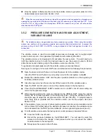
Page 31: ...10 Lo Q RPT active caution indicator 11 Reservoir shut off valve 12 Variable volume pressure generation 13 Variable volume piston position indicator Figure 9 E DWT 10000 AF front view 1 TEST port 2 Sy...

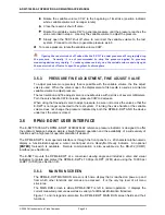
Page 32: ...9 and Figure 10 for an E DWT schematic and view when following this procedure Leave an open purge point for example a loose fitting at the highest point possible in the test system that is connected...

Page 33: ...DWT view and schematic when following this procedure Open the reservoir shut off valve to connect the reservoir to the variable volume Close the TEST shut off valve to avoid pulling oil out of the te...

Page 34: ...he fine adjust valve to adjust pressure be sure not to close the valve so that the E DWT is no longer connected to the test system If turning the valve handle or the variable volume does not change th...

Page 35: ...utoZ is ON blank AutoZ is OFF 3 9 1 6 RR Active Q RPT position indicator Indicates the position of the active Q RPT in the RPM4 E DWT Hi Hi Q RPT Lo Lo Q RPT 3 1 1 7 nn nn Sequence progress indicator...

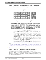
Page 36: ...ayout Pressing ENT generally causes execution or forward movement in the menu tree Pressing ESC moves back in the menu tree and or causes execution to cease or suspend Pressing ESC repeatedly eventual...

Page 37: ...1 SUMMARY Table 3 provides a brief summary of RPM4 E DWT direct function key operation It may be useful to keep a copy of this summary near the E DWT especially when first becoming acquainted with it...

Page 38: ...sing the RANGE function key activates the range viewing and selecting function When the RANGE function key is first pressed the active range is displayed For example 1 Q RPT designator 2 Type of range...

Page 39: ...to any configuration of six units see Section 3 9 6 Internally RPM4 E DWT always operates in Pascal Pa the SI unit of pressure Values of pressure are represented in other units by the application of...

Page 40: ...optimize its measurement characteristics and features for a specific user defined pressure range of operation PRINCIPLE RPM4 E DWT A70M A7M AF is designed to support the calibration and test of a very...

Page 41: ...e full scale pressure Enter the full scale pressure value in the entry field and press ENT If the full scale value entered cannot be covered by RPM4 E DWT an error message appears View proposed AutoRa...

Page 42: ...To run a leak check first set the pressure to the desired leak check pressure Changing the pressure in a test system causes adiabatic temperature changes in the pressurized medium that need to have d...

Page 43: ...heck was run 3 7 7 DISPLAY PURPOSE To select from a variety of choices the information that is displayed on the second line of the RPM4 E DWT display PRINCIPLE RPM4 E DWT supports a variety of advance...

Page 44: ...PM4 E DWT active range with minimal additional information is desired OPERATION To set the DISPLAY function press DISPLAY from the main run screen The display is 1Avg 2Rate 3Dev 4RPT 5Hi Lo 6Freez 7Cl...

Page 45: ...alues Average screen Pressing ENT while in the Average DISPLAY aborts the current averaging period and causes a new one to begin ENT can thus be use to trigger a new averaging period on demand In the...

Page 46: ...ability setting or the Ready Not Ready condition The Rate DISPLAY is the default RPM4 E DWT main run screen display To go to a DISPLAY other than Rate press DISPLAY and make a new DISPLAY choice see S...

Page 47: ...er Q RPT to be displayed on the second bottom line of the RPM4 E DWT display is referred to as the inactive Q RPT It is inactive in the sense that all Q RPT specific functions and settings such as UNI...

Page 48: ...Hi Lo DISPLAY active the main run screen is 1 Highest pressure observed since Hi Lo reset 2 Lowest pressure observed since Hi Lo reset 9911 psi g zHi H 9922 L9800 The Hi Lo values change each time a n...

Page 49: ...ive the Freeze value defaults back to zero To go to a DISPLAY other than Freeze press DISPLAY and make a new DISPLAY choice see Section 3 7 7 3 7 7 7 Clean PURPOSE To activate the Clean DISPLAY See Se...

Page 50: ...and the test medium can be changed using SPECIAL 3Head see Section 3 9 3 An oil head has a pressure value of about 0 04 psi inch 0 1 kPa cm As a general rule with RPM4 E DWT A70M A7M AF use of the HEA...

Page 51: ...tion 3 9 1 Principle for a full explanation of the AutoZ function The RPM4 E DWT should be zeroed prior to running a calibration or test with the E DWT OPERATION For the AutoZ function key to run Auto...

Page 52: ...the RPM4 E DWT see Section 3 7 5 to the range of the DUT being tested with settings appropriate for the tolerance of the DUT Step the operator through a planned sequence of test pressure increments if...

Page 53: ...ection for information on running a Quick or File AutoTest See Section 3 8 5 2 for information on setting up File AutoTest files See Section 3 8 5 1 for information on viewing the data files that resu...

Page 54: ...e user to check that the correct test has been defined or selected and that it does not exceed the range of the device or system being tested 1 Indication of minimum and maximum pressure included in t...

Page 55: ...ading is in Ready condition the RPM4 E DWT makes a valid entry sound and the display is 1 Standard RPM4 E DWT run screen indicating current measured pressure 2 Number of this test point the total numb...

Page 56: ...utoRange function creates a range and automatically sets various operating parameters proportionally to the range see Section 3 7 5 Operating settings can then be changed by the user Many operating se...

Page 57: ...ge to be deleted is displayed press ENT If you are sure you want to delete this range press ENT again in response to the Delete query ESC returns to the AutoRange screen without deleting a range To de...

Page 58: ...tive stability limit to make a Ready Not Ready determination see Section 3 1 2 The stability function allows the stability limit to be adjusted by the user to increase or decrease the stability requir...

Page 59: ...ew or edit upper limit of the active range press SETUP 4UL The display is 1 Entry field for upper limit value in active pressure unit of measure and measurement mode Upper limit Hi 10200 psi g Edit th...

Page 60: ...nt is logged The logged pressure measurements and an identifying header are stored in a data file The data file can be viewed immediately following the last point of the sequence by selecting 1data In...

Page 61: ...indicating that the AutoTest was a File AutoTest or QA indicating a Quick AutoTest This is preceded by OT if the test point was out of tolerance definition of out of tolerance is Set point RPM4 E DWT...

Page 62: ...TUP 5ATest 2file Select 1view to view an AutoTest definition file Select 2edit to edit an AutoTest definition file When 2edit is selected the display is Edit File AutoTest 1 Enter the number 1 40 of t...

Page 63: ...SPECIAL from the MAIN RUN screen to access the SPECIAL menu The display is 1AutoZ 2remote 3head 4SDS 5prefs 6Punit 7intern 8cal 9reset Some screens such as the SPECIAL menu go beyond the two lines pr...

Page 64: ...TEST shut off valve is open and the TEST port is disconnected and filled with oil to the weep hole reference level 2 Pu 0 The absolute pressure reading of the Q RPT with no AutoZ offset at the time Au...

Page 65: ...ENT to activate the new value Press ESC to abandon changes There is no reason to edit Poffset during normal RPM4 E DWT operation or maintenance Poffset should only be adjusted using AutoZ see Section...

Page 66: ...carriage return and 10 line feed and usually should not be changed 3 9 2 2 3IEEE 488 An IEEE 488 interface is not included in the E DWT A70M A7M AF model 3 9 2 3 4FORMAT The RPM4 E DWT has two differe...

Page 67: ...see Section 3 9 2 1 to set the COM ports COM1 or COM2 is defective The reason for failed communications is almost always a cable or incorrect RS232 interface settings Be sure that these are correct b...

Page 68: ...0 idle minutes The screen saver activation time can be adjusted by the user or screen saving can be completely eliminated Setting screen saver time to zero eliminates the SCREEN SAVER function so that...

Page 69: ...and date 3 9 5 4 4ID PURPOSE To view or edit the RPM4 E DWT user ID and to view the RPM4 E DWT serial number OPERATION To access the ID function press SPECIAL 5prefs 4ID Select 1view to view the curr...

Page 70: ...g environments as follows None This level is intended for use only by the system manager and or calibration facility It allows access and editing in all areas including critical metrological informati...

Page 71: ...ef 3time make changes SPECIAL 5pref 4ID 2edit SPECIAL 6Punit SPECIAL 7intern SPECIAL 7intern 3RPT2x NOT USED SPECIAL 7interrn 5log clear log SPECIAL 8cal SPECIAL 8cal 2edit under any selection SPECIAL...

Page 72: ...eld xx increments each time a secondary password is used The third field pppppp is for user entry of the normal password The factory secondary password is available in case the user s password has bee...

Page 73: ...er Pascal Pa in the entry field Pressing ENT defines the user unit and returns to the Set up unit n screen The user defined unit label can be customized to any alphanumeric four character label using...

Page 74: ...7 3 The display resolution is fixed to 0 1 Pa or its equivalent 3 9 7 2 2READRT PURPOSE To turn ON and OFF RPM4 E DWT s automated rate of change dependent reading integration and display rate feature...

Page 75: ...specific Turning auto read rate ON or OFF in one range turns it ON or OFF for all RPM4 E DWT ranges 3 9 7 3 3RPT2X PURPOSE This feature is not used in this RPM4 E DWT model 3 9 7 4 4LO VNT PURPOSE Thi...

Page 76: ...ctory defaults These may include settings vital to RPM4 E DWT operation and affecting the calibration of the reference pressure transducers RPTs Reset functions should only be used by qualified person...

Page 77: ...2 Lo Vnt Automatic None ReadRate Automatic 3 9 7 2 3 9 9 2 2 UNITS PURPOSE Sets the pressure units available under the UNIT function to default selections depending see Section 3 7 3 Sets the user de...

Page 78: ...g critical calibration data Combines all resets in one global reset command that clears the entire user section of non volatile memory except the ID function see Section 3 9 5 4 and the security level...

Page 79: ...was sent to the unit 4 2 1 RS232 INTERFACE 4 2 1 1 COM1 The RPM4 E DWT COM1 RS232 interface is located on the back of the unit It is a 9 pin male DB 9F connector configured as a DCE device Data is tr...

Page 80: ...Section 3 9 2 3 or remotely using the L2 or L3 program message see Section 4 4 4 The MSGFMT command can also be used to select the format but is not recommended for new designs The main difference bet...

Page 81: ...is cleared every time a new program message is received Examples COM1 enhanced mode command CLS or CLS Clear the error queue Wait for reply UNIT KPA or UNIT KPA Generates a reply User must wait for r...

Page 82: ...Read the power up memory test status MSGFMT Read or set the type of program message format to use PCALn Read or set the user Lo Q RPT calibration information PCAL XX Read or set the user Lo Q RPT cal...

Page 83: ...erpressure may result ERR 13 Text queue overflow ERR 14 User unit not defined ERR 17 Not used ERR 18 Command not yet available ERR 19 Not available with absolute units ERR 20 Not available with gauge...

Page 84: ...mands support an optional suffix This suffix is used to specify a Q RPT to which the command applies since many settings are Q RPT specific Suffix of 1 for Hi Q RPT access Suffix of 2 for Lo Q RPT acc...

Page 85: ...t is terminated with a carriage return Line feeds are discarded This will discontinue when the next query is sent to the RPM4 E DWT There is no other reply from this program message Prior to using thi...

Page 86: ...easurement mode specified The reply indicates the current range data including the Q RPTLabel used for the range If inWa is specified for the unit the temperature reference can be given after the unit...

Page 87: ...N Remarks The RPM4 E DWT AutoZ function can be turned ON and OFF Example enhanced Cmd sent Query reply AUTOZERO 0 0 No reply if GPIB 488 Example classic Sent Query reply AUTOZERO 0 AUTOZERO 0 Errors E...

Page 88: ...RPM4 E DWT When the COM1 port configuration of the RPM4 E DWT is changed the program message reply COM1 use only is sent at the old COM1 settings but all subsequent communications are accomplished at...

Page 89: ...rical only format YYYYMMDD Remarks The RPM4 E DWT has an internal real time calendar clock The span of acceptable dates ranges from 19800101 to 20791231 The reply is always in the YYYYMMDD format Exam...

Page 90: ...ent identification label Command Query ID string ID Classic ID string ID Arguments String An alphanumeric string up to 12 characters long Remarks The user defined ID label can be used to allow the use...

Page 91: ...orrupted and was set to factory defaults 1 The memory was found to be OK on power up Example classic Sent Reply MEM MEM 0 RPM4 E DWT data corrupted and was set to factory defaults MEM 1 The memory was...

Page 92: ...L2 2 1 1 000021 20011201 2 10 Pa 1 000021 20011201 No reply if GPIB 488 Example enhanced Cmd sent Query reply PCAL 2 1 1 000021 20011201 2 10 Pa 1 000021 20011201 Example enhanced Cmd sent Query reply...

Page 93: ...97 000 kPa g See Also PR QPRR SR 3 6 1 3 1 2 3 9 7 1 QPRR Purpose Read the last Q RPT pressure measurement pressure rate and on board barometer output immediately Query QPRR Classic QPRR Optional Suf...

Page 94: ...be used instead of RptLabel 1 Specify the Hi Q RPT 2 Specify the Lo Q RPT Remarks The next available pressure rate of change in the current pressure unit per second is returned After receiving this p...

Page 95: ...a 1 See Also SR 3 1 2 REMOTE Purpose Lock out the front panel keypads during remote operation Command REMOTE Classic REMOTE Remarks The RPM4 E DWT goes into remote mode whenever communications take pl...

Page 96: ...t panel screen RptLocator Text field identifying the Q RPT position in the RPM4 E DWT system IH identifies this as an internal Hi Q RPT IL identifies this as an internal Lo Q RPT Serial The serial num...

Page 97: ...OL The pressure of one of the active Q RPTs has exceeded the user defined upper or lower limits OP The pressure of one of the Q RPTs has exceeded the Q RPT s maximum limits ER An internal device fail...

Page 98: ...clock Command Query TIME hh mmXX TIME Classic TIME hh mmXX TIME Arguments hh mm XX The time in a 12 hour format using a colon delimiter am or pm Example enhanced Cmd sent Query reply TIME 12 52PM 12...

Page 99: ...o 3 9 6 3 7 3 ULn Purpose Read or set an upper limit for the specified or active Q RPT Command Query Uln limit Uln Classic Uln limit ULn Optional Suffix n A suffix may be used instead of RptLabel 1 Sp...

Page 100: ...ter of the reply is always g for gauge mode White spaces precede this character if needed The temperature reference is added to the reply only if the unit is InWa The reply includes the measurement mo...

Page 101: ...Q RPT pressure offset for absolute measurement mode Pa The Q RPT pressure offset for differential measurement mode Pa Note the AbsOffset DifOffset are not used in this model Remarks The pressure offs...

Page 102: ...E DWT 10000 AF OPERATION AND MAINTENANCE MANUAL 2008 DH Instruments a Fluke Company Page 92 N NO OT TE ES S...

Page 103: ...or failure use this manual and other training facilities to become thoroughly familiar with E DWT operation For rapid assistance in specific situations see Chapter 6 for troubleshooting information Un...

Page 104: ...ometer press SPECIAL 7intern 3baro from the main run screen A pressure standard may be connected to the on board barometer by connecting to one of the ATM ports on the RPM4 E DWT rear panel Q RPT modu...

Page 105: ...he coefficients affect the Q RPT reading following Corrected reading uncorrected reading PM PA PA is expressed in units of pressure always the SI unit Pascal PM is dimensionless Since the RPM4 E DWT o...

Page 106: ...00 F DH500 F gland and collar type fitting for coned and left hand threaded 1 4 in OD tube equivalent to AE F250C HIP HF4 etc The E DWT TEST port connects to BOTH of the RPM4 E DWT A70M A7M AF referen...

Page 107: ...F Support Disk and can be downloaded from www dhinstruments com 5 3 6 EDITING AND VIEWING Q RPT CALIBRATION INFORMATION PURPOSE View and or edit Q RPT calibration information fields including The cali...

Page 108: ...reen ENT in edit mode goes to confirmation of change activation if changes have been made in any of the calibration screens Pressing ESC in any edit screen exits the edit screen without activating any...

Page 109: ...RPT or 2Lo Q RPT 2edit and write the new calibration date and the new values of PA and PM for the Q RPT calibrated see Section 5 3 6 Calculate as left data for the calibration if desired following as...

Page 110: ...panel Using a 7 mm wrench remove the nuts and lock washers from the front of the RPM4 E DWT side rack mount bracket Then remove the nuts washers and lock washers from both ends of the rear rack mount...

Page 111: ...holding the bottom panel and cover together turn the RPM4 E DWT over and place it bottom side down q Lift the top cover off of the bottom panel leaving the front and rear panels behind with the botto...

Page 112: ...ximum pressure of the A70M is 10 000 psi 70 MPa The rupture disk is designed to rupture at 11 500 psi 79 3 MPa Prior to reaching this pressure a high pitched audible alarm will sound indicating that P...

Page 113: ...kbench Be careful not to scrape or damage the coned tube tip as this is where the high pressure seal is made A damaged tip can result in fluid leaks To help ease the reassembly process remove the othe...

Page 114: ...e procedure When reassembling the high pressure gland and collar fittings protect the conical tip from damage and be sure that the collar is fully threaded on the nipple left hand thread before tighte...

Page 115: ...is used for temperature compensation of the barometric sensor 5 5 5 4 Q RPT MODULE The Q RPT module is an integrated Quartz Reference Pressure Transducer Q RPT assembly The module includes a Q RPT bra...

Page 116: ...fluorescent display 5 5 5 6 COOLING FAN The cooling fan is mounted on the RPM4 E DWT rear panel and connected to the main board It is a 12V brushless DC fan 5 5 6 HYDRAULIC SCHEMATIC OF Q RPT MODULE F...

Page 117: ...Screw M4 x 10 3153285 2 Nut 3153914 2 Lock washer 3153147 1 Priming pump assembly 3338698 1 Vent assembly 3338705 1 Reservoir lid 3327974 1 Right side panel 3329385 2 Handle 3308993 1 RPM4 E DWT A70M...

Page 118: ...ble DC power 3335962 1 Cable LED assembly 3122849 1 Rack mount bracket rear support 3329122 1 VV mounting bracket 3329073 4 Screw M4 x 12 3153285 12 Washer M4 3153079 6 Lock washer M4 3153914 6 Nut M4...

Page 119: ...on 3143366 1 Safety tee with Safety head 3330814 1 Rupture disk 3330463 1 Tube weld 3337407 1 Adaptor high pressure 3330799 1 Adaptor 3068564 1 RPM4 E DWT 3337317 2 Valve shut off 3328687 2 Knob valve...

Page 120: ...E DWT 10000 AF OPERATION AND MAINTENANCE MANUAL 2008 DH Instruments a Fluke Company Page 110 Figure 18 E DWT detailed hydraulic schematic...

Page 121: ...ear panel external view illustrated parts breakdown see Figure 19 REQUIRED DESCRIPTION PART NO 1 DC Power jack 1765470 1 J1 ACC connector 3122919 1 Cover plate 3331706 1 Rear panel 3329105 1 Fan 12V 3...

Page 122: ...20 REQUIRED DESCRIPTION PART NO 1 Manifold A7M AF 3148653 1 Plug ss 3151095 1 Manifold A70M 3151088 14 Screw M3 3154248 14 Lock washer M3 3153752 2 Adaptor barb 3137843 4 O ring 5 193 3136506 2 Union...

Page 123: ...ART NO 1 Tubing vinyl 3232608 1 Adaptor 3140570 1 Micro board 3156058 1 Electronic chassis 3148892 5 Nut 3149280 12 Lock washer M3 3153752 5 Screw M3 3152908 1 Tubing polyurethane 3232477 1 Cable asse...

Page 124: ...illustrated parts breakdown see Figure 22 REQUIRED DESCRIPTION PART NO 1 Ribbon cable 3151805 5 Lock washer 3153752 1 Nut M3 2678004 2 Standoff M3 3137784 4 Screw M3 3154248 9 Washer 3152972 1 Retaine...

Page 125: ...o much not enough resolution Resolution setting needs to be changed Change resolution setting using the resolution function using AutoRange or by initializing an AutoTest 3 8 2 3 7 5 3 7 11 Can t incr...

Page 126: ...ntaneous value Average DISPLAY 3 7 7 3 7 7 1 These is a leak in the pressure system to which E DWT is connected Find and correct leak Consider using RPM4 E DWT leak check function 3 7 6 The pressure a...

Page 127: ...Familiarize yourself with your E DWT schematic Close reservoir shut off valve 3 5 Too much air in test system to which E DWT is connected The test system must be filled with oil and primed before pre...

Page 128: ...E DWT 10000 AF OPERATION AND MAINTENANCE MANUAL 2008 DH Instruments a Fluke Company Page 118 N NO OT TE ES S...

Page 129: ...ble 24 Pressure unit of measure conversion coefficients TO CONVERT FROM Pa To MULTIPLY BY Pa Pascal 1 0 Mbar millibar 1 0 E 02 hPa hecto Pascal 1 0 E 02 kPa kilo Pascal 1 0 E 03 Bar Bar 1 0 E 05 mmWa...

Page 130: ...E DWT 10000 AF OPERATION AND MAINTENANCE MANUAL 2008 DH Instruments a Fluke Company Page 120 N NO OT TE ES S...

Page 131: ...this warranty such indirect damage includes but is not limited to loss of production profits revenue or goodwill even if DH Instruments has been advised of the possibility thereof and regardless of wh...

Page 132: ...E DWT 10000 AF OPERATION AND MAINTENANCE MANUAL 2008 DH Instruments a Fluke Company Page 122 N NO OT TE ES S...

Page 133: ...in the positive direction above atmosphere Head A difference in height between the RPM4 E DWT reference level and the DUT HiLo A DISPLAY function in which the highest and lowest pressure measurements...

Page 134: ...icated pressure is the average of their measurements SDS Self Defense System A system to protect Q RPTs from overpressure made up of isolation and vent valves and internal operating logic SDS is not u...

Reviews: