19
Input pin should be connected to the Controller’s Output pin.
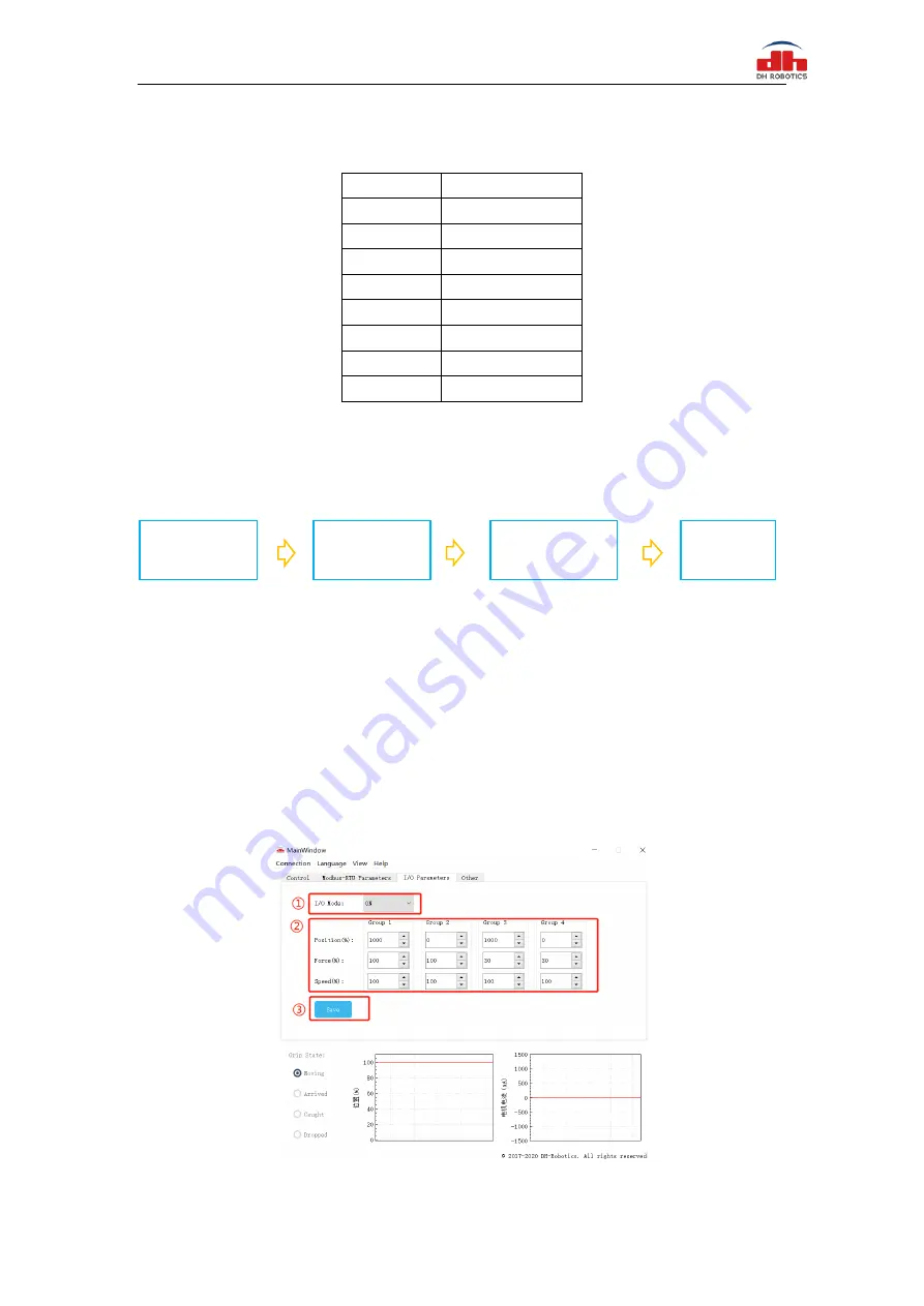
Table 3.3 wire Description
Wire color
Description
White
485_A
Brown
485_B
Green
OUTPUT 1
Yellow
OUTPUT 2
Grey
24 V
Pink
INPUT 2
Blue
INPUT 1
Red
GND
3.2 I/O Setting
The diagram of IO operation steps is as follows:
3.2.1 Configure IO
Connect 24 V, GND and 485_ A and 485_ B. Then you can use
I/O Parameter Configuration
to configure four groups of IO parameters .It is recommended to use serial port debugging software
at PC for configuration. IO parameters are configured as continuous address, and 12 groups of data
including 0x0405-0x0410 need to be set.
You can configure the IO parameters of the gripper in two ways, as follows:
The first way:
Use the test software of the gripper for configuration. As shown in figures 3.1 (a) and 3.1 (b)
Figure 3.1 (a) graphical configuration
Step 1:
Configure IO
parameters
Step 2:
Open IO
mode
Step 3:
Save Settings
save
Step 4:
Restart


