30
DHOLLANDIA
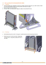
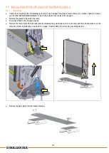
Maneuver the ramp and ramp frame back into position. Slide the ramp frame over the articulation pin on the base plate. Mount
the washer, spring washer and bolt, and tighten the bolt with the required torque. See appendix 11.2 on page 42.
Engage the quick-release lock at the opposite side.
The quick-release lock is adjustable in length. It is set at the factory, but verify this during installation to make sure the ramp
frame is very solidly attached to the ramp fixations.
To adjust the length, release the nut on the threaded part of the lock. Turn the eye to shorten or lengthen the lock. Fasten the
nut firmly after final adjustment.
8.5.5
Additional ramp fixations for a 2
nd
travel position of the ramp inside the vehicle [option OAF821]
Option OAF821 provides ramp fixations for a second travel position alongside the side panel of the vehicle body.
Turn the ramp 90° inwards to locate the correct position of ramp fixations. Verify with the installation dimensions provided in
section 7.4 from page 14 onwards.
Mark the drill points. Proceed with drilling and installation as described in previous steps.
Summary of Contents for DH-AI02.04.01
Page 10: ...9 DHOLLANDIA DH AI12 04 01 TERMINOLOGY DH AI13 04 01 TERMINOLOGY...
Page 11: ...10 DHOLLANDIA DH AI12 10 01 TERMINOLOGY Portable ramp DH AI02 04 01 TERMINOLOGY...
Page 15: ...14 DHOLLANDIA 7 4 TECHNICAL SPECIFICATIONS DH AI12 04 01...
Page 16: ...15 DHOLLANDIA DH AI12 10 01...
Page 17: ...16 DHOLLANDIA DH AI13 04 01...
Page 18: ...17 DHOLLANDIA DH AI02 04 01...


