27
EN
DHOLLANDIA
4.5
EX.
4.6
G
M
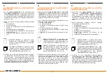
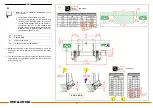
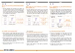
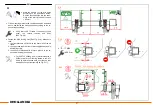
Mount the supports at dimension P on the FIT-
TING DRAWING or the TECHNICAL SUM-
MARY of the HTL. P is the height from the top
of the loading floor of the vehicle, to the top side
of the temporary mounting support
[See Fig. 4.5].
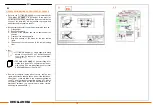
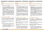
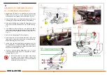
Next, lift up the platform (by hoist, forklift, overhead gantry
crane,...), and position it onto the mounting supports. Ad-
just and centre its position, so that it stands perfectly
aligned in the rear frame of the vehicle body [See Fig. 4.6].
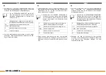
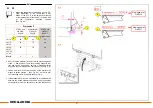
Fasten and secure the final position of the platform by
means of hoists, clamps, ... [See Fig. 4.4], in order to pre-
vent mounting errors, accidental fall and injury.
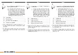
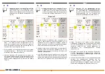
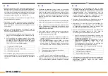
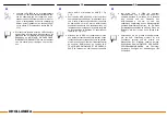
If the standard HTL is to be mounted with a rubber seal kit
between the closed platform and vehicle body, the position
of the platform must be adjusted to suit the thickness of
1
2
!
STEEL new
OAP310/
S245.R
ALUMINIUM
OAP310/
S245.R
STEEL old
OAP311/
S245.F
round edge
round edge
straight edge
LM.15,
LM.20
70 70 48
LM.30,
LM.35,
LSU.40,
LV.40
78 78 60
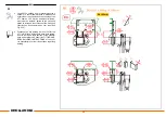
Dimension P
Dim. D
5 2 2
LM.10 64 64 48
1
2
2
New option ref.
OAP310
New option ref.
OAP311


