28
DHOLLANDIA
If the mounting plates are too high and interfere with the subframe or cross-bearers of the vehicle body, they can be shortened in
height, but with respect for the minimum requirements for the bolts and other instructions in this chapter.
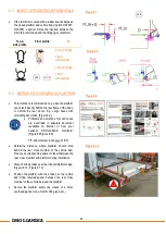
Mark the position of the drill holes on the mounting plates, vehicle chassis and subframe, according to the instructions above.
Drill the holes (ø of the drill bit = M-value of the bolts + 0.5mm).
Fit the mounting plates and bolts to the vehicle chassis and subframe. Fasten all mounting bolts on the lift frame and the chassis
with the required torque.
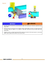
NOTICE
During installation, the bolts and nuts must be fastened to the adequate torque, prescribed in these mounting instructions.
If you use mounting bolts not supplied by DHOLLANDIA, obtain confirmation of the required torque from your supplier.
Check and retighten bolts after the static and dynamic weight test performed at the end of the mounting procedure.
NOTICE
Where chassis beams, subframes and other steel chassis or body components have been cut, grinded, drilled, etc…, the
installer should apply adequate anti-corrosive coating to protect the vehicle and body against corrosion. Check, and make sure
you comply with the instructions of the vehicle manufacturer.
9.3
ADDITIONAL REMARKS OF HEAVY DUTY LIFTS AND VERY LONG PLATFORMS
Following additional instructions apply or all tail lifts ≥ 3000kg capacity, and / or platform depths ≥ 2300mm.
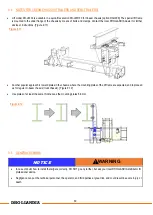
The part of the mounting plates overlapping the subframe must be additionally fastened:
1.
By 2 additional bolts [Figure 9.9]
2.
By 2 weld seams [Figure 9.10]
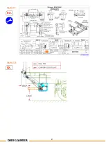
If the vertical distance H2 between the underside of the chassis and the top face of the lift frame ≥ 100mm, an additional
reinforcement must be welded or bolted to increase the stiffness of the mounting plates [reinforcement R1 in Figure 9.8]
If less than 2/3 of the mounting plates overlap the chassis and subframe, higher mounting plates must be implemented [Figure
9.10]:
1.
Inquire at DHOLLANDIA if longer plates are available
2.
Or extend the plates according to the instructions given
The add-on part of the mounting plates must be fastened:
1.
By 2 additional bolts [option 1 Figure 9.10]
2.
By 2 weld seams [option 2 Figure 9.10]
Summary of Contents for DH-LM Series
Page 11: ...10 DHOLLANDIA 1 2 9 8 11 2 13 4 7 11 5 v 3 v 10 Figure 6 1 14 6 v...
Page 13: ...12 DHOLLANDIA Figure 6 2 MTG MFT...
Page 27: ...26 DHOLLANDIA Figure 9 6...
Page 34: ...33 DHOLLANDIA Figure 9 15...
Page 42: ...41 DHOLLANDIA EX EX Figure 11 9 Figure 11 10...
Page 46: ...45 DHOLLANDIA Figure 14 1 EX...
Page 50: ...49 DHOLLANDIA Figure 16 2 400mm 400mm 250mm 400mm 400mm 250mm...
Page 52: ...51 DHOLLANDIA EF0583 LM EN EF0565 EN EF0620 EN EF0570 CAP serial nr EF0564 EN EF0581 EN xxxx...
Page 58: ...57 DHOLLANDIA...
Page 59: ...58 DHOLLANDIA...
Page 60: ...59 DHOLLANDIA...
Page 68: ...67 DHOLLANDIA Figure 18 4 Figure 18 5...
Page 70: ...69 DHOLLANDIA For option OAE510 15 see Figure 18 7 below Figure 18 7...


