background image


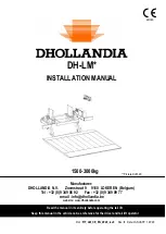
DHOLLANDIA 

4


SAFETY PRECAUTIONS FOR OPERATION 


It is essential that the personnel involved in installing, servicing and repairing  tail lifts knows, understands and 
applies the safety instructions and precautions contained in the OPERATION MANUAL issued with the tail lift. 


Therefore, make sure you consult the OPERATION MANUAL prior to installing or operating the tail lift. 


5


SAFETY PRECAUTIONS FOR INSTALLATION 


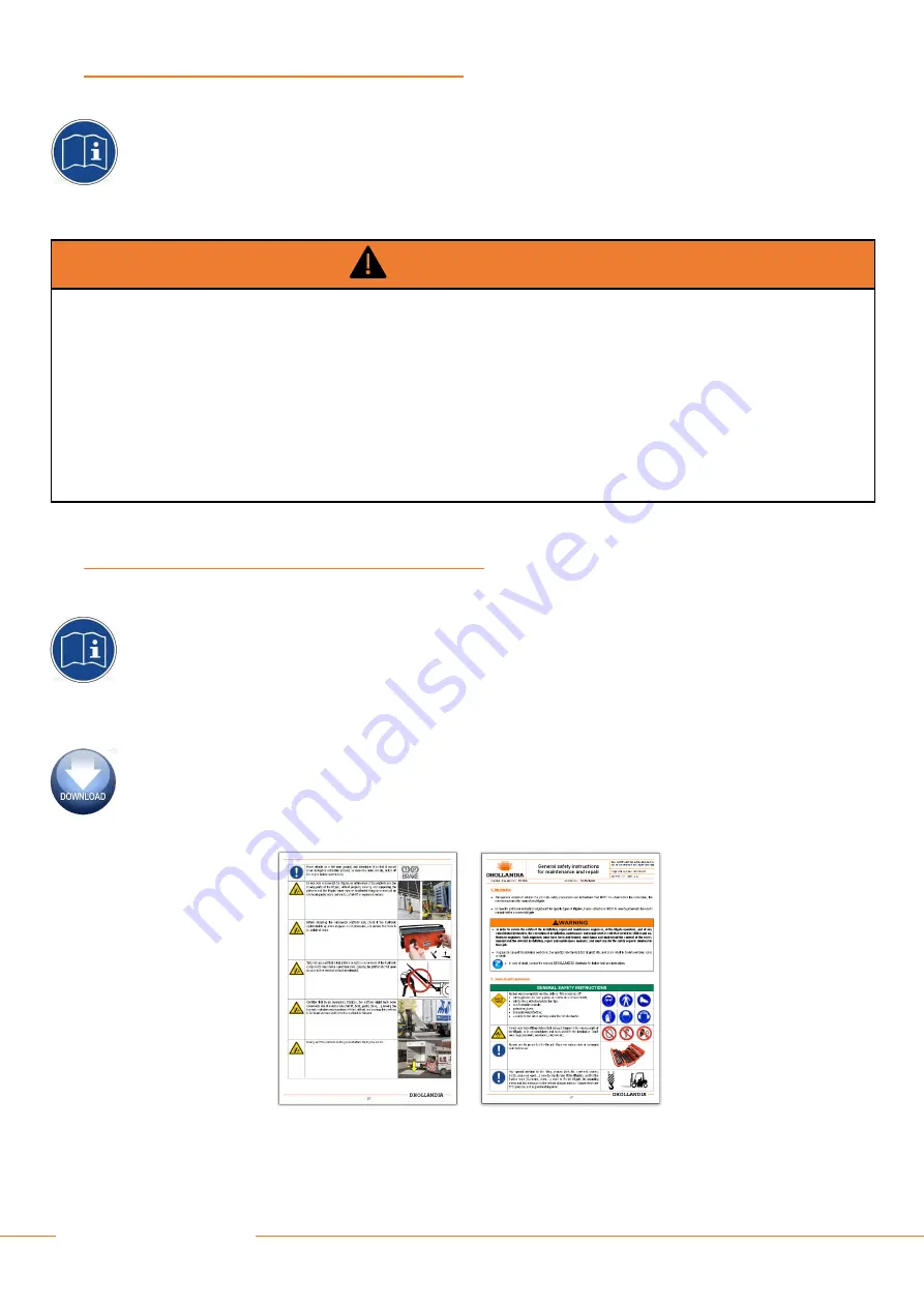
It is essential that the personnel involved in installing, servicing and repairing tail lifts knows, understands and 
applies  the  safety  instructions  and  precautions  contained  in  the  GENERAL  SAFETY  INSTRUCTIONS  FOR 
INSTALLATION, MAINTENANCE AND REPAIR manual. 


Therefore,  make  sure  you  consult  the  GENERAL  SAFETY  INSTRUCTIONS  FOR  INSTALLATION, 
MAINTENANCE AND REPAIR manual prior to installing the tail lift. 


These instructions are supplied as a separate manual with your tail lift. 


You can also contact your national DHOLLANDIA distributor for the latest edition of this manual. See page 5 for 
contact info. Or download the latest edition from the website:  
www.dhollandia.com  your language  Downloads → User’s manuals → General information 


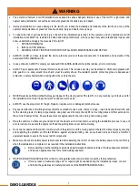
WARNING 


Improper use of the tail lift will put the operator and other parties at great risk of serious bodily injury and death. 


To reduce the risk of serious bodily injury to the operator and any bystanders, the use of the  tail lift is restricted to skilled 
operators, who have been properly trained, and who know and understand the full contents of the operation manual. 


To reduce the risk of serious bodily injury or death, THE OPERATOR MUST COMPLY WITH ALL SAFETY INSTRUCTIONS 
AND WARNING LABELS IN THE OPERATION MANUAL before and while operating the tail lift. 


Please confirm you have reviewed the most up-to-date version of this manual prior to installation and operation of the associated 
DHOLLANDIA tail lift. 

Summary of Contents for DH-LM Series

Page 1: ...gium Tel 32 0 9 349 06 92 Fax 32 0 9 349 09 77 e mail info dhollandia be website www dhollandia com DH LM INSTALLATION MANUAL Read the manual in its entirety before operating the tail lift Keep this m...

Page 2: ...frame 23 9 2 Fixation of the mounting plates 25 9 3 Additional remarks of heavy duty lifts and very long platforms 28 9 4 Notes for I beam chassis trailers and semi trailers 30 9 5 General remark 30 9...

Page 3: ...lts supplied with tail lift 60 18 4 PDI checklist 1 2 62 18 5 Safe operator position on the platform 65 18 6 2 button portable control 66 18 7 Circuit breaker 70 18 8 Cab cut off switch 71 18 9 Electr...

Page 4: ...ch if not avoided will result in death or serious injury white letters on red background WARNING indicates a potentially hazardous situation which if not avoided could result in death or serious injur...

Page 5: ...gations in terms of periodic testing and certification DHOLLANDIA tail lifts are regularly being adapted to new vehicle and chassis developments and specialized customer requirements Therefore DHOLLAN...

Page 6: ...that results from operating a tail lift that has been modified from the original design without explicit written approval from the manufacturer DHOLLANDIA disclaims liability for any personal injury d...

Page 7: ...uctions are supplied as a separate manual with your tail lift You can also contact your national DHOLLANDIA distributor for the latest edition of this manual See page 5 for contact info Or download th...

Page 8: ...hinery and tools used for the installation Don t wear rings bracelets necklaces watches etc ALWAYS use the proper tool for the job Repair or replace worn or damaged tools before use Pay special attent...

Page 9: ...2 for prescribed torque values Welding should be done by qualified personnel only and only to the extent allowed by the vehicle manufacturer Ensure that the positive and ground cables are disconnected...

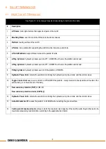
Page 10: ...the platform and its load 8 Tilting Cylinders hydraulic cylinders used to tilt the platform UP DOWN 9 Hydraulic Power Unit contains the electric motor driving the hydraulic pump the oil tank and the c...

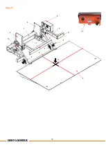
Page 11: ...10 DHOLLANDIA 1 2 9 8 11 2 13 4 7 11 5 v 3 v 10 Figure 6 1 14 6 v...

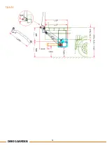
Page 12: ...e of chassis to top of the vehicle floor MFT Mounting height of lift frame under the vehicle measured from the top of vehicle floor to the top of the lift frame main tube Mounting height Floor to Tube...

Page 13: ...12 DHOLLANDIA Figure 6 2 MTG MFT...

Page 14: ...n body width with pump unit in premounted position Body Width Outside BCI Width of the mid panel Body Cut Inside BCW Width of the cut outs for the lift arms and tilt cylinders Body Cut Width BLB Avail...

Page 15: ...he tail lift are present Compare the voltage of the vehicle batteries with the voltage of the hydraulic pump unit of the tail lift Compare the installation dimensions and maximum installation paramete...

Page 16: ...c Do not release the locking bolts of the auto tilt brackets on the lift frame before the tail lift installation is fully finished Figure 6 4 7 INSTALLATION DIMENSIONS If an INSTALLATION DRAWING is av...

Page 17: ...on the installation drawing or can be calculated as follows Ex For vehicle with 1250mm bed height Fitting height MFT 1250 140 2 555mm You might want to deviate from the initial mounting height MFT Ex...

Page 18: ...ht MFT is measured from the top of the vehicle bed to the centre of the lift arm articulation pin See Figure 7 5 Figure 7 6 how this is measured for tail lifts with mechanical or hydraulic auto tilt a...

Page 19: ...ues Figure 7 3 The arm width LAC and the position of the pump unit determine the min width of the vehicle body BWO MIN The arm width lac further determines the width of the mid panel BCI the position...

Page 20: ...Figure 7 9 Refer to sources mentioned above for values Modify the rear part of the vehicle to suit the chosen mounting parameters NOTICE Where chassis beams longs sills the rear sill and other steel c...

Page 21: ...asure the outside width across the lift arms This dimension corresponds with the inside width needed between the 2 fitting jigs Mark the centreline of the vehicle on the rear cross member of the vehic...

Page 22: ...nto the mounting supports Slide a spacer D 5mm between the platform and the rear frame of the body Figure 8 5 Adjust and centre its position Ensure the platform stands perfectly aligned to the rear fr...

Page 23: ...ernet or from your national DHOLLANDIA distributor Figure 8 9Figure 8 8 FIT LM container locks yyyy 01 EN Determine distance where platform should stop behind the rear cross member of the vehicle bed...

Page 24: ...LIFT FRAME Position the lift frame on a wheeled jack order code M0025 Figure 9 1 or use a similar device to slide the frame under the chassis of the vehicle Slide the lift frame under the chassis and...

Page 25: ...can move freely Figure 9 4 In case of bolt on mounting plates fit the mounting plates over the frame Do not tighten the nuts at this stage Ensure the lift frame is positioned conforming to the mountin...

Page 26: ...welding spatters If any welding works are done to the mounting plates all hoses must be adequately covered and protected e g by a leather welding blanket When the hydraulic system is under pressure f...

Page 27: ...26 DHOLLANDIA Figure 9 6...

Page 28: ...s over the full surface of the plates overlapping the vehicle chassis and subframe Figure 9 7 Figure 9 8 WARNING Position and mount the mounting plates and bolts carefully following the instructions N...

Page 29: ...el chassis or body components have been cut grinded drilled etc the installer should apply adequate anti corrosive coating to protect the vehicle and body against corrosion Check and make sure you com...

Page 30: ...installer should ensure compliance with the instructions of the vehicle manufacturer on chassis connections and lift installations Reinforcement R1 if H2 100 Reinforcement R2 if H2 H1 3 DH LM 30 DH L...

Page 31: ...proach is to weld plates in the chassis where the mounting plates of the lift frame are expected and to proceed as for regular C beam chassis truck chassis Figure 9 12 Use plates of at least the same...

Page 32: ...ng plate by means of 3 bolts and the bolts fastened with the adequate torque Figure 9 13 Figure 9 15 In case the RUP is supplied as separate kit the same applies for the stiffeners 5 Additionally the...

Page 33: ...nstalled according to DHOLLANDIA s instructions and all bolts fastened with the adequate torque see appendix It is not allowed to modify these constructions without prior written approval from DHOLLAN...

Page 34: ...33 DHOLLANDIA Figure 9 15...

Page 35: ...ves on the lift cylinders manually Figure 10 2 2 Loosening up the hydraulic couplings of oil pipes connected to the cylinder to eliminate vacuum forces 3 Pushing pulling the piston rod by hand 4 Mount...

Page 36: ...me way as originally supplied on the platform Figure 10 3 Figure 10 4 Tilt the platform open to 45 angle Align the hole in the tilt cylinders with the hole in the platform hands by means of the electr...

Page 37: ...gs or by hydraulic pump optional Rods will react quickly and suddenly when releasing pressure The platform is very heavy Handle with caution If platform is dropped it may cause serious personal injury...

Page 38: ...iciently strong to sustain the forces induced by the lift cylinders at maximum working pressure over the expected life time of the tail lift Verify effect of arm stops on platform alignment at vehicle...

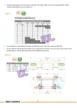
Page 39: ...sions 3 and locking nuts 2 mounted to the extremity of the tilt cylinders 1 Figure 11 6 Use electric function CLOSE to slide out tilt cylinders to their maximum length Figure 11 Loosen up the locking...

Page 40: ...39 DHOLLANDIA Max 10mm A1 A2 LM 15 LM 20 LM 30 LV 40 LM 15 LM 20 LM 30 LV 40 Figure 11 6 Figure 11 6 Figure 11 7 Figure 11 7 Figure 11 8...

Page 41: ...OF THE RUPD The RUPD Rear Underrun Protection Device is optional and if applicable is normally premounted on the lift frame If not premounted install the RUPD according to the installation drawing in...

Page 42: ...41 DHOLLANDIA EX EX Figure 11 9 Figure 11 10...

Page 43: ...ehicle manufacturers often impose prescribed connections for the battery and earth connections of the lift which should be observed to avoid damage to the vehicle electrics Where such prescriptions co...

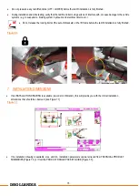
Page 44: ...ic mounting jack Remove the C clamps chains and hoists and other support means that have been used during installation Push the DOWN button to lower the platform to the ground Remove the locking bolts...

Page 45: ...r installation and once in service with intervals as indicated in the user s manual Use the grease gun to pump in grease until a grease collar is formed on both sides of the bearing or articulation th...

Page 46: ...45 DHOLLANDIA Figure 14 1 EX...

Page 47: ...e of the platform point 3 If applicable connect the flashing platform lights and verify their function If the operator is allowed to travel up and down on the platform the installer must mark a safe w...

Page 48: ...47 DHOLLANDIA Apply the safety decals to the tail lift and vehicle body before delivery to the customer conform with instructions shown on opposite side Figure 15 6 Max 1 500 kg Figure 15 6...

Page 49: ...e extension plate 4 Correct stowage of the tail lift in its travel position Make sure that the tail lift will be clearly visible in surrounding traffic Figure 1 Apply the RD WH visibility tape on both...

Page 50: ...49 DHOLLANDIA Figure 16 2 400mm 400mm 250mm 400mm 400mm 250mm...

Page 51: ...ly replaced Get free replacement decals from DHOLLANDIA Contact your regional DHOLLANDIA distributor See page 3 for contact info The operator should comply with all affixed safety and instructions dec...

Page 52: ...51 DHOLLANDIA EF0583 LM EN EF0565 EN EF0620 EN EF0570 CAP serial nr EF0564 EN EF0581 EN xxxx...

Page 53: ...ENFR LIFTGATE DECALS USED AND AFFIXED IN AREAS OTHER THAN THE REAR OF THE VEHICLE A Cabin switch in driver s cabin to switch electrical power to liftgate on off if so equipped B For circuit breaker i...

Page 54: ...icular tail lift or when ordering replacement parts 2 In addition to the tail lift type and serial number the various serial number labels provide additional information such as the maximum rated lift...

Page 55: ...parts Crushing shearing hazard Keep hands away from moving parts Crushing shearing hazard Keep feet away from moving parts Slipping hazard Tripping hazard Hazard caused by tilting objects Hazard of f...

Page 56: ...ovision lever valve creating an emergency exit Unlock Disengage the mechanical locking system Lock Engage the mechanical locking system Switch ON the electrical power Switch ON the electrical power to...

Page 57: ...ludes grease plans for the most frequent tail lifts DH LM 10 DH LM 15 DH LM 20 DH LM 30 For special lifts grease plans can deviate Contact the national DHOLLANDIA distributor for further assistance or...

Page 58: ...57 DHOLLANDIA...

Page 59: ...58 DHOLLANDIA...

Page 60: ...59 DHOLLANDIA...

Page 61: ...CE WARNING Incorrect too soft or too hard tightening of mounting bolts can lead to accidental fall of the tail lift off the vehicle chassis A fall of the tail lift off the chassis can damage the tail...

Page 62: ...16 x 2 143 lbs ft 195 lbs ft Fine M14 x 1 5 99 lbs ft 136 lbs ft M16 x 1 5 155 lbs ft 195 lbs ft M20 x 1 5 129 lbs ft lbs ft M24 x 2 136 lbs ft lbs ft Banjo Bolt Torque Specifications BSPP Banjo Bolt...

Page 63: ...and secured All articulation pins are equipped with lube fittings and are lubricated Areas of drilling cutting grinding welding etc are adequately protected against corrosion 3 Inspection of the elec...

Page 64: ...de sufficiently visible for the surrounding traffic platform lights flags reflective tape traffic cones At vehicle floor level the platform aligns flush with the extension plate A hand grip for the op...

Page 65: ...ntation for the operator The OPERATION MANUAL and MAINTENANCE MANUAL are available in the vehicle NOTICE WARNING The PDI check list completes the final quality inspection of the installation Once comp...

Page 66: ...LANDIA recommends that the installer mounts a handgrip to the rear frame of the vehicle body Such handgrip will enable the operator to ALWAYS maintain 3 points of contact while lifting or lowering on...

Page 67: ...he cable 6 is protected against physical damage Run the cable inside the rear post of the vehicle body or mount a steel protection plate over it If the tail lift is equipped with a main external contr...

Page 68: ...67 DHOLLANDIA Figure 18 4 Figure 18 5...

Page 69: ...68 DHOLLANDIA A general wiring schematic for gravity down with the two button handheld control is shown in Figure 18 6 Figure 18 6...

Page 70: ...69 DHOLLANDIA For option OAE510 15 see Figure 18 7 below Figure 18 7...

Page 71: ...70 DHOLLANDIA 18 7 CIRCUIT BREAKER A resettable circuit breaker option is also available for the connection to the batteries Figure 18 8 Figure 18 8...

Page 72: ...ce in Figure 18 9 to properly connect the E0667 illuminated cab switch Figure 18 9 Figure 18 10 For orders that shipped with option OAE510 15 refer to Figure 18 11 to properly connect the cab switch F...

Page 73: ...are recommended battery cables and ground cables Recommended MIN cable sections for battery cables and ground cables Size electric motor Cable section 500 W 16 mm 5 AWG 1200 2200 W up to max 1500kg ca...

Page 74: ...ly available hydraulic oil is used in the majority of DHOLLANDIA lifts sold for use in normal climate conditions This includes all countries excluding the Nordic countries suffering very cold winter c...

Page 75: ...DHOLLANDIA service agents Only authorized OEM DHOLLANDIA replacement parts should be used for all repairs Consult the separate MAINTENANCE AND REPAIR MANUAL for safety instructions maintenance guideli...

Reviews: