background image

49 

EN 

DHOLLANDIA 

9.10 

 ! 

 ! 

• 

Thoroughly grease all grease nipples in the 
various articulations with acid-free grease, ac-
cording to the grease plan in the annex. 


• 

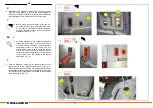
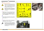
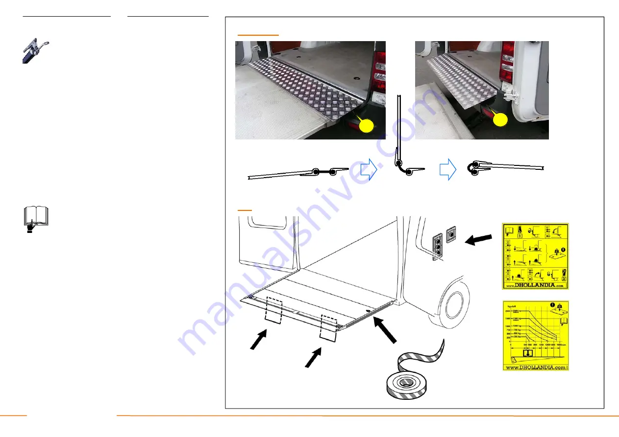
Fit all features that will create a safe working environment 
for the operator, and the strangers in public traffic: [See 
Fig. 9.10] 


1.  If a wander lead with spiral cable is adopted as auxil-

iary control unit, clearly and permanently mark the safe
-working zone on the loading floor of the vehicle, and 
on the platform surface, according to the instructions 
given in FIT-ELEC-OPTION-2008-02A. 

2.  Fit the platform flags and / or check the correct work-

ing order of the electric flashing lights on the platform. 

3.  Apply red/white reflective marker tape on both sides of 

the platform. 

4.  Apply the sticker with the operation instructions near 

the control box, in direct sight of the operator when 
using the HTL. 


• 

Execute the complete put-into-service test, on 
the basis of the CHECKLIST FOR WEIGHT 
TEST AND COMMISSIONING included in 
chapter 3 of the user’s manual. 

9.9 - S243.B 
Summary of Contents for DH-LSP 300-500kg

Page 1: ...tie wenst over gewijzigde onderdelen gelieve uw offici le Dhollandia agent te contacteren voor advies Haftungsausschluss Die in diesem Handbuch enthaltenen Abbildungen und Informationen sind nicht ver...

Page 2: ...componenten 54 A 3 Smeerplan DH LSP 05 56 A 4 Elektrische en hydraulische schema s 58 0 LISTE DES ABREVIATIONS 4 1 INSTRUCTIONS GENERALES DE MONTAGE 6 2 TRAVAIL PREPARATOIRE SUR LA CARROSSERIE LE CHA...

Page 3: ...cipal HTL components 55 A 3 Grease plan DH LSP 05 57 A 4 Electric and hydraulic diagrams 59 0 LISTE DER ABK RZUNGEN 4 1 ALLGEMEINE MONTAGEANLEITUNGEN 6 2 VORBEREITUNGSARBEITEN AN FAHRZEUGKAROSSERIE CH...

Page 4: ...Attire l attention sur un l ment en particulier sur un dessin ou une illustration R f rences chiffr es entre le texte l illustra tion ou entre deux illustrations ex cuter sym triquement sur les deux c...

Page 5: ...is incorrect Study in detail Example not for all models identical Drawing attention to a particular item in a drawing or illustration Numbered references between text illustra tion or between 2 illus...

Page 6: ...outes les pi ces n ces saires pour monter le HEH correctement ont t livr es Comparez le voltage des batteries du v hicule au voltage du groupe hydraulique du HEH Comparez les dimensions de montage men...

Page 7: ...ocument Check the following points before getting started Check if the kit is complete and if all parts needed to fit the HTL correctly have been delivered Compare the voltage of the batteries of the...

Page 8: ...e batterijklemmen en ABS stekkers Werk de LKP af in overeenstemming met de verkeerswet geving van het land waarin het voertuig zal worden gere gistreerd Laswerk mag uitsluitend worden uitgevoerd door...

Page 9: ...d ABS plugs during fitting Finish the HTL in accordance with the road legislation of the country where the vehicle will be registered Welding should be done by qualified personnel only and only to the...

Page 10: ...nhalten ggf genauere Details f r jede individuelle HLB In einigen Abbildungen dieser Montageanleitung wird angegeben dass sie ein Beispiel sind d h dass sie nicht f r alle und jedes HLB Modell das in...

Page 11: ...individual lift type Some illustrations in these fitting instructions therefore mention that they are an example which means that they don t apply to each and every lift model covered by this handboo...

Page 12: ...r dans le pare chocs arri re incompatibles avec le HEH Consultez le fabricant du v hicule pour trouver des solu tions de remplacement ex modifications au tuyau d chappement types de profil s pare choc...

Page 13: ...s of the ex haust pipe access step integrated in the rear bumper that are not compatible with the HTL Consult with the vehicle manufacturer for replacement solutions e g ex haust pipe modifications mo...

Page 14: ...adapteront qu un seul type bien sp cifique de v hicule Disposez les flasques de montage sur le sol pr tes l emploi et positionnez le b ti du HEH sur un chariot de montage roulettes ou un chariot l vat...

Page 15: ...with the HTL will suit only one specific type of vehicle Lay the mounting plates ready on the ground and position the HTL frame on a wheeled fitting jack or fork lift that will later be used to slide...

Page 16: ...urnies dans le kit Otez l exc dent de mas tic ou de peinture si n cessaire pour pouvoir pendre les flasques de montage correctement Positionnez les flasques correctement contre le soubassement du ch s...

Page 17: ...Fit the mounting plates to the vehicle chassis using the bolts supplied in the kit Remove the excess of mastic or paint if required to hang the mounting plates correctly Push up the plates into corre...

Page 18: ...orrosion zinc en spray Dinitriol sur les trous fra chement perfor s dans le ch ssis et laissez s cher Ins rez les tubes de renfort dans le ch ssis voir Fig 3 5 positionnez correctement les flasques de...

Page 19: ...e tube See Fig 3 4 Apply an anti corrosive protection zinc spray Dinitrol to the freshly made chassis perfora tions and allow to dry Insert the reinforcement tubes into the chassis see Fig 3 5 fit the...

Page 20: ...ten in het onderste deel van de montageplaten Zie Fig 4 2 Monteer het frame van de LKP op de montage platen door middel van 6 x M16 bouten die meegeleverd worden met de LKP bout naar buiten wijzend en...

Page 21: ...lower part of the mounting plates See Fig 4 2 Fit the lift frame to the mounting plates by means of the 6 x M16 bolts supplied with the HTL bolt pointing outside and fasten the fit ting bolts to the r...

Page 22: ...schar nierpennen van het platform 2 aan de linkerkant 3 aan de rechterkant Zie Fig 5 1 Verwijder vervolgens de 2 scharnierpennen die voorge monteerd zijn in het platform Zie Fig 5 2 Let bij het ver w...

Page 23: ...m 2 on left side 3 on right side See Fig 5 1 Then remove the 2 articulation pins which are pre mounted in the platform away from the platform See Fig 5 2 When doing so note the correction position and...

Page 24: ...partant de la surface int rieure travers du plateau Au dos du plateau remontez les crous de bloca ge et les embouts de graissage dans leur posi tion d origine Voir Fig 5 6 Connectez la tige de stabili...

Page 25: ...he grease nipples as reference point Mount the locking bolts starting from the inside surface through the platform At the backside of the platform mount the locking nuts and grease nipples back in the...

Page 26: ...ons du constructeur ce sujet si vous avez opt pour une mise la masse directe du moteur lectrique et les vannes du HEH au ch ssis du v hicule Si un retour par la masse isol est n cessaire tez le morcea...

Page 27: ...rth if you choose for a direct earth of the electromotor and valves of the HTL to the vehicle chas sis follow the manufacturer s instructions on this behalf If an insulated earth return is required re...

Page 28: ...d huile et aux circuits de c blages du v hicule Assurez vous que c est fix l aide de brace lets tous les 10 cm Voir Fig 6 4 Les c bles 35mm de batterie et de masse peuvent tre fix s au ch ssis au moy...

Page 29: ...ed to the suspen sion the breaking systems oil pipes and wiring circuits of the vehicle Ensure adequate fixation by means of cable ties every 10 cm See Fig 6 4 The 35mm battery cable and earth cable c...

Page 30: ...tterie du v hicule Serrez fermement toutes les connexions vis s es au coupe circuit et au fusible 300A du HEH voir plus bas Un montage mal ou insuf fisamment serr peut mener des faux contacts et la su...

Page 31: ...e battery switch to the vehicle battery Fasten all bolted connections to the battery switch and the 300A fuse for the HTL see be low firmly Loose and insufficient fitting can lead to bad contact and o...

Page 32: ...e dans la cabine du v hicule ou du compartiment moteur jusqu la borne n gative de la batterie du v hicu le Serrez fermement la connexion la masse et prot gez la contre la corrosion comme vous l avez f...

Page 33: ...mm earth cable from the entry point in the vehicle cabin or the engine compart ment to the negative pole of the vehicle battery Firmly fasten the earth connection and protect against corrosion in the...

Page 34: ...les r gle ments de s curit de l U E pr voient une distance de 400 mm avec une tol rance de 100 mm entre le cadre arri re et l axe central du bo tier de commande externe Voir Fig 7 1 D finissez la pos...

Page 35: ...f the body and the raising or closing platform As a compromise between the 2 points the CE Safety regulations foresee that the distance between the rear edge of the body and the centre line of the ext...

Page 36: ...tiers de commande sur la carrosserie du v hicule l aide de boulons auto perceuses en inox ou percez les trous pour recourir en suite des rivets ou boulons en acier inoxyda ble Finissez le montage des...

Page 37: ...of the control boxes before drilling the holes Mount the control boxes to the vehicle body by means of stainless steel self drilling screws or drill holes and use stainless steel rivets or bolts Finis...

Page 38: ...ble lectrique au bloc de connexion lectrique pr vu cet effet R f rez vous aux notes que vous avez prises pr c demment lors de la d connexion du c blage ou suivez le sch ma de c blage en annexe Voir Fi...

Page 39: ...onnect the separate cores of the electrical cable to the electric con nection block foreseen on this behalf Follow your earlier notes on disconnecting the wiring or follow the wiring diagram in the an...

Page 40: ...le long du tuyau hydraulique flexible du v rin d inclinaison vers le groupe hydraulique et fixez les l aide de bracelets tous les 5 cm Assurez vous que les c bles ne puissent pas tre endommag s compr...

Page 41: ...tilt cylinder See Fig 8 2 Run all electrical cables originating from the platform alongside the flexible hydraulic hose of the tilt cylinder towards the hydraulic power pack and fasten them with cabl...

Page 42: ...l endroit o il est possible de prendre le signal lectri que pour cette lampe et finissez en le monta ge Consultez les instructions de montage FIT ELEC OPTION 2008 02A pour les questions de montage et...

Page 43: ...S from the vehicle manufacturer to establish how and where the electrical signal for this light can be taken and finish the instal lation of it Consult the fitting instructions FIT ELEC OPTION 2008 02...

Page 44: ...soulever et se fer mer Enlevez les accessoires de montage qui restent l vateur grue sur portique du plateau Fermez le groupe hydraulique et verrouillez le gauche ou droite l aide des boulons de blocag...

Page 45: ...e purpose to assure that the platform is supported hydraulically abort this ac tion as soon as you see the platform lift and close Re move the remaining fitting aids hoist overhead gantry crane from t...

Page 46: ...s v rins hydrauliques Pour effectuer une purge compl te soulevez l arri re du v hicule Commencer de la plateforme en position route 1 Ouvrez la plateforme compl tement plus loin que la position horizo...

Page 47: ...and closed position are adjusted execute all functions at least 2 times so that the hydraulic cylinders can be purged In order to execute a complete purge keep the rear of the vehicle elevated from t...

Page 48: ...s curis e sur le plancher de chargement du v hicule et sur la surfa ce du plateau conform ment aux instructions repri ses dans le FIT ELEC OPTION 2008 02A 2 Placez les drapeaux de plateforme et ou v...

Page 49: ...one on the loading floor of the vehicle and on the platform surface according to the instructions given in FIT ELEC OPTION 2008 02A 2 Fit the platform flags and or check the correct work ing order of...

Page 50: ...oir Fig 9 11 Ensuite scellez la soupape de lib ration de la pression Apr s avoir accompli avec succ s les tests de mise en service et les tests pratiques en poids rev rifiez et r vi sez les param tres...

Page 51: ...ift capacity of the HTL See Fig 9 11 Seal the pressure relief valve after that After satisfactory completion of the put into service test and the practical weight tests double check and revise the set...

Page 52: ...pour boulons en N m M Les couples de serrage de toutes les connexions boulonn es doivent tre v rifi s une fois que vous aurez termin les tests en charge statique et dy namique obligatoires la fin du p...

Page 53: ...Fine M14 x 1 5 135 195 M16 x 1 5 208 300 M24 x 2 450 Prescribed tightening moment M N m M20 x 1 5 360 A 1 M ANNEXES A 1 Prescribed tightening torques for bolts in N m The tightening torques of all bo...

Page 54: ...que ANH NGE A 2 bersicht der wichtigsten HLB Komponenten N Umschreibung 1 Bedieneinheit Bedienungskasten 2 Plattform 3 Mechanische Plattformverriegelung 4 Plattform Hand 5 Montageplatte 6 Hubwerk der...

Page 55: ...trol box 2 Platform 3 Platform lock 4 Platform hand 5 Mounting plate 6 HTL frame 7 Lift arm 8 Lift cylinder 9 Tilt cylinder 10 Spring cylinder 11 Stabiliser rod 12 Hydraulic memory cylinder 13 Articul...

Page 56: ...56 NL FR DE DHOLLANDIA M M BIJLAGEN A 3 Smeerplan DH LSP 05 ANNEXES A 3 Plan de graissage DH LSP 05 M ANH NGE A 3 Schmierplan DH LSP 05 13 Schmierstellen 13 points de graissage 13 smeerpunten F F F...

Page 57: ...57 EN DHOLLANDIA M ANNEXES A 3 Grease plan DH LSP 05 A 3 11 1 1 2 2 3 3 4 4 5 5 6 7 8 9 10 13 12 13 grease points F...

Page 58: ...des sch mas peut galement tre t l charg e de notre site internet www dhollandia com Autres r f rences importantes 1 Voir manuel FIT ELEC GENERAL 2008 02A pour les sch mas du raccordement des c bles d...

Page 59: ...also be downloaded from our internet website www dhollandia com Other important references See manual FIT ELEC GENERAL 2008 02A for the wiring diagrams of the battery cable and the earth cable See www...

Page 60: ......

Page 61: ......

Reviews: