background image

18 


DHOLLANDIA 


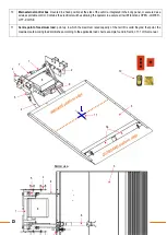
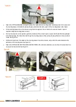
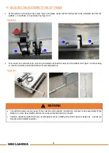
Unmount the mounting plates again and drill the larger holes for the reinforcement tubes (if required by the vehicle 
manufacturer), using a drill of the same diameter as the outside diameter of the little tube. See Figure 8.4. 


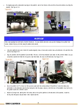
Apply an anti-corrosive protection (zinc-spray, Dinitrol,…) to the freshly made chassis perforations, and allow to dry. 


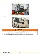
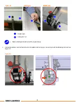
Insert the reinforcement tubes into the chassis (see Figure 8.5), fit the mounting plates into correct position, and fasten the bolts 
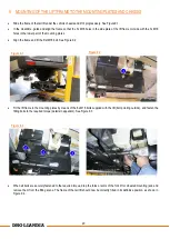
through the mounting plates and the chassis to the prescribed torque (details in appendix). See Figure 8.6. 


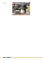
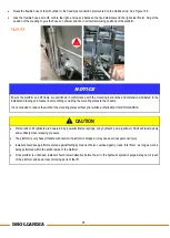
Terminate the fitting of the mounting plates as on Figure 8.7 opposite. 


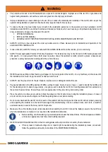
WARNING 


Incorrect installation of the mounting plates and bolts can lead to accidental fall of the tail lift off the vehicle chassis. 


A fall of the tail lift off the chassis can damage the tail lift and / or vehicle chassis and can cause serious bodily injury or death 
to the operator and any bystanders. 


Therefore, it is essential that the mounting plates are installed following the instructions of this manual. 

Figure 8.4 


Figure 8.5 


Summary of Contents for DH-LSP

Page 1: ...Tel 32 0 9 349 06 92 Fax 32 0 9 349 09 77 e mail info dhollandia be website www dhollandia com DH LSP INSTALLATION MANUAL Read the manual in its entirety before operating the tail lift Keep this manu...

Page 2: ...THE PLATFORM TO THE LIFT FRAME 22 11 CONNECTING THE POWER PACK OF THE TAIL LIFT TO THE VEHICLE BATTERIES 26 12 MOUNTING THE CONTROL BOX OF THE TAIL LIFT 31 13 OTHER ELECTRICAL CONNECTIONS 34 14 PUTTIN...

Page 3: ...ch if not avoided will result in death or serious injury white letters on red background WARNING indicates a potentially hazardous situation which if not avoided could result in death or serious injur...

Page 4: ...in terms of periodic testing and certification DHOLLANDIA tail lifts are regularly being adapted to new vehicle and chassis developments and specialized customer requirements Therefore DHOLLANDIA res...

Page 5: ...that results from operating a tail lift that has been modified from the original design without explicit written approval from the manufacturer DHOLLANDIA disclaims liability for any personal injury d...

Page 6: ...uctions are supplied as a separate manual with your tail lift You can also contact your national DHOLLANDIA distributor for the latest edition of this manual See page 4 for contact info Or download th...

Page 7: ...hinery and tools used for the installation Don t wear rings bracelets necklaces watches etc ALWAYS use the proper tool for the job Repair or replace worn or damaged tools before use Pay special attent...

Page 8: ...2 for prescribed torque values Welding should be done by qualified personnel only and only to the extent allowed by the vehicle manufacturer Ensure that the positive and ground cables are disconnected...

Page 9: ...le chassis 3 Platform carries the load during loading unloading lifting lowering Manufactured from light weight aluminium and with a non slip working surface 3a Platform stow lock mechanical lock to p...

Page 10: ...l switches allowing the operator to execute all tail lift functions OPEN LOWER LIFT CLOSE 11 Centre point of maximum load point up to which the maximum rated capacity of the tail lift is valid Beyond...

Page 11: ...ns together while the tail lift is stowed in its travel position 3e Cart stops usually 2 load restraint flaps mounted just near the outboard platform edge Depending on options chosen the cart stops fe...

Page 12: ...11 DHOLLANDIA 9 1 2 2 11 3a Bottom view 10 4 4 5 6 7 8 5 8 2 1 3 3a 3 3b 3c 3d 3b 3c 3d 3e 5 9...

Page 13: ...ly fit the tail lift are present Compare the voltage of the vehicle batteries with the voltage of the hydraulic pump unit of the tail lift Compare the installation dimensions and maximum installation...

Page 14: ...before the tail lift installation is fully finished During installation and while testing verify that the tail lift and its moving parts don t interfere with or cause damage to the vehicle systems e g...

Page 15: ...underside of the vehicle so that the fitting work can be performed in a relaxed and safe manner Figure 7 1 Remove the spare wheel carrier part of the exhaust pipe and any other components interfering...

Page 16: ...lates and the fitting drawing supplied with the tail lift will suit only one specific type of vehicle Lay the mounting plates ready on the ground and position the tail lift frame on a wheeled fitting...

Page 17: ...ing note that welding on galvanized parts releases hazardous fumes Provide adequate ventilation and wear an appropriate toxic fume rated welding respirator It is strongly recommended to first grind of...

Page 18: ...es into correct position against the underside of the vehicle chassis to assure that the tail lift will hang straight in the finished stage Then fasten the bolts through the mounting plates and the ex...

Page 19: ...orrect position and fasten the bolts through the mounting plates and the chassis to the prescribed torque details in appendix See Figure 8 6 Terminate the fitting of the mounting plates as on Figure 8...

Page 20: ...shown in these installation instructions If you use mounting bolts not supplied by DHOLLANDIA make sure the total strength is at least equivalent as per this manual Check and retighten the bolts after...

Page 21: ...he frame and fit the first M16 bolt See Figure 9 2 Fit the lift frame to the mounting plates by means of the 6x M16 bolts supplied with the lift bolt pointing outside and fasten the fitting bolts to t...

Page 22: ...21 DHOLLANDIA Figure 9 4...

Page 23: ...from the platform See Figure 10 2 When doing so note the correction position and direction of every articulation pin WARNING The platform sections are very heavy In the current mounting position the p...

Page 24: ...platform and the platform hand with the 2 lift arms and fit the articulation pins back into the platform Make sure you correct their position and direction long pin on right hand side short pin on lef...

Page 25: ...ts with the required torque Connect the stabilizer rod to the fixation hand on the platform with the hinge pin Secure the pin with the M8 locking bolt nut See Figure 10 7 LEFT arm RIGHT arm Figure 10...

Page 26: ...to the chassis It is not allowed to reduce the width of the mounting plates without prior written authorization from DHOLLANDIA CAUTION Piston rods of tilt cylinders are powered in by powerful interna...

Page 27: ...arter solenoid in the power pack to the incoming pole of the battery switch in the vehicle cabin or the main fuse on the battery if no battery switch is mounted see below See Figure 11 2 Regarding the...

Page 28: ...his class can sustain a temperature of 100 C continuously and 125 C peak Seek an adequate routing to run the 35mm battery cable and earth cable to the vehicle battery Ensure that the wiring cannot be...

Page 29: ...e chassis area to the inside of the vehicle cabin without drilling extra holes See Figure 11 5 If a battery switch will be used to isolate the main power to the electric motor which is strongly recomm...

Page 30: ...can lead to bad contact and overheating of the connections followed by premature failing of the power circuit Apply a thick layer of anti corrosive grease or Vaseline to all electric connections and...

Page 31: ...cable from the entry point in the vehicle cabin or the engine compartment to the negative pole of the vehicle battery Firmly fasten the earth connection and protect against corrosion in the same way...

Page 32: ...e legal requirements given in Figure 12 1 the position and shape of any awkward reinforcements in the side panel of the vehicle body the control boxes require a flat surface for mounting and the heigh...

Page 33: ...ith a water tight seam of silicone both on the inside as on the outside of the vehicle body See Figure 12 4 Mount the control boxes to the vehicle panel preservation against corrosion Seek an adequate...

Page 34: ...ct the separate cores of the electrical cable to the electric connection block foreseen for this purpose Follow your earlier notes on disconnecting the wiring or follow the wiring diagram in the appen...

Page 35: ...ylinder Run all electrical cables originating from the platform alongside the flexible hydraulic hose of the tilt cylinder towards the hydraulic power pack and fasten them with cable ties every 2 5cm...

Page 36: ...r to establish how and where the electrical signal for this light can be connected and finish the installation Consult the fitting instructions TEC ELEC 02 EN for fitting and safety details regarding...

Page 37: ...h regards to the correct use of the different lift functions and of the safety aspects linked to tail lift use See Figure 14 1 for a summary of the main functions Use the functions lift and close to b...

Page 38: ...lift to adjust the end stops for the lift arms and to set and limit the lifting height of the horizontal platform Adjust the stroke of the M16 bolts on the left and right side of the lift frame and fi...

Page 39: ...ction open for another 20 sec see Figure 14 6 2 Tilt the platform back up to horizontal position and lower the platform completely further down below normal ground level until the lift cylinders are f...

Page 40: ...les in the various articulations with acid free grease according to the grease plan in the appendix Thoroughly grease all grease nipples in the various articulations with acid free grease according to...

Page 41: ...ontrol box in direct sight of the operator when using the tail lift Safety markings Execute the complete put into service test on the basis of the CHECKLIST FOR WEIGHT TEST AND COMMISSIONING included...

Page 42: ...ated in the user s manual Use the grease gun to pump in grease until a grease collar is formed on both sides of the bearing or articulation that will protect it from ingress of water salt sand and dir...

Page 43: ...42 DHOLLANDIA Figure 15 1...

Page 44: ...43 DHOLLANDIA...

Page 45: ...44 DHOLLANDIA...

Page 46: ...paint a safe work zone of 400mmx400mm at a safe distance of 250mm removed from the hazardous crushing area between the inboard platform edge and the extension plate Figure 16 2 Work through the PDI c...

Page 47: ...46 DHOLLANDIA Figure 16 3 Figure 16 2 400mm 400mm 250mm 400mm 400mm 250mm...

Page 48: ...ly replaced Get free replacement decals from DHOLLANDIA Contact your regional DHOLLANDIA distributor See page 4 for contact info The operator should comply with all affixed safety and instructions dec...

Page 49: ...48 DHOLLANDIA EF0583 LM EN EF0565 EN EF0620 EN EF0570 CAP serial nr EF0564 EN EF0581 EN xxxx...

Page 50: ...ENFR LIFTGATE DECALS USED AND AFFIXED IN AREAS OTHER THAN THE REAR OF THE VEHICLE A Cabin switch in driver s cabin to switch electrical power to liftgate on off if so equipped B For circuit breaker i...

Page 51: ...icular tail lift or when ordering replacement parts 2 In addition to the tail lift type and serial number the various serial number labels provide additional information such as the maximum rated lift...

Page 52: ...parts Crushing shearing hazard Keep hands away from moving parts Crushing shearing hazard Keep feet away from moving parts Slipping hazard Tripping hazard Hazard caused by tilting objects Hazard of f...

Page 53: ...ovision lever valve creating an emergency exit Unlock Disengage the mechanical locking system Lock Engage the mechanical locking system Switch ON the electrical power Switch ON the electrical power to...

Page 54: ...CE WARNING Incorrect too soft or too hard tightening of mounting bolts can lead to accidental fall of the tail lift off the vehicle chassis A fall of the tail lift off the chassis can damage the tail...

Page 55: ...16 x 2 143 lbs ft 195 lbs ft Fine M14 x 1 5 99 lbs ft 136 lbs ft M16 x 1 5 155 lbs ft 195 lbs ft M20 x 1 5 129 lbs ft lbs ft M24 x 2 136 lbs ft lbs ft Banjo Bolt Torque Specifications BSPP Banjo Bolt...

Page 56: ...and secured All articulation pins are equipped with lube fittings and are lubricated Areas of drilling cutting grinding welding etc are adequately protected against corrosion 3 Inspection of the elec...

Page 57: ...de sufficiently visible for the surrounding traffic platform lights flags reflective tape traffic cones At vehicle floor level the platform aligns flush with the extension plate A hand grip for the op...

Page 58: ...ntation for the operator The OPERATION MANUAL and MAINTENANCE MANUAL are available in the vehicle NOTICE WARNING The PDI check list completes the final quality inspection of the installation Once comp...

Page 59: ...LANDIA recommends that the installer mounts a handgrip to the rear frame of the vehicle body Such handgrip will enable the operator to ALWAYS maintain 3 points of contact while lifting or lowering on...

Page 60: ...he cable 6 is protected against physical damage Run the cable inside the rear post of the vehicle body or mount a steel protection plate over it If the tail lift is equipped with a main external contr...

Page 61: ...60 DHOLLANDIA Figure 18 4 Figure 18 5...

Page 62: ...61 DHOLLANDIA A general wiring schematic for gravity down with the two button handheld control is shown in Figure 18 6 Figure 18 6 To positive post on motor solenoid To ground post on pump motor...

Page 63: ...62 DHOLLANDIA For option OAE510 15 see Figure 18 7 below Figure 18 7 To positive post on motor solenoid To ground post on pump motor...

Page 64: ...63 DHOLLANDIA A general wiring schematic for power down with the two button handheld control is shown in Figure 18 8 Figure 18 8 To positive post on motor solenoid To ground post on pump motor...

Page 65: ...64 DHOLLANDIA For option OAE510 15 see Figure 18 9 below Figure 18 9 To positive post on motor solenoid To ground post on pump motor...

Page 66: ...65 DHOLLANDIA 18 6 CIRCUIT BREAKER A resettable circuit breaker option is also available for the connection to the batteries Figure 18 10 Figure 18 10...

Page 67: ...e in Figure 18 11 to properly connect the E0667 illuminated cab switch For orders that shipped with option OAE510 15 refer to Figure 18 13 to properly connect the cab switch Figure 18 13 Figure 18 11...

Page 68: ...or battery cables and ground cables Size electric motor Cable section 500 W 16 mm 5 AWG 1200 2200 W up to max 1500 kg capacity length 7 m 1200 2200 W up to max 1500 kg capacity length 7 m 25 mm 3 AWG...

Page 69: ...ly available hydraulic oil is used in the majority of DHOLLANDIA lifts sold for use in normal climate conditions This includes all countries excluding the Nordic countries suffering very cold winter c...

Page 70: ...DHOLLANDIA service agents Only authorized OEM DHOLLANDIA replacement parts should be used for all repairs Consult the separate MAINTENANCE AND REPAIR MANUAL for safety instructions maintenance guideli...

Reviews: