55
DHOLLANDIA
18.3
PDI CHECKLIST 1/2
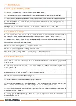
1 - General inspection on the fitting parameters
The vehicle is technically suitable for the type of lift and its max. rated capacity.
The requirement for mechanical or hydraulic stabilizing legs has been checked and been fulfilled (if applicable).
The actual fitting dimensions don’t exceed the theoretical maximum fitting dimensions mentioned in the fitting drawings.
The lift has been fitted to conform with the fitting instructions of DHOLLANDIA, and the Body Building Guidelines of the
OEM vehicle manufacturer.
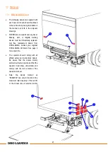
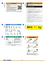
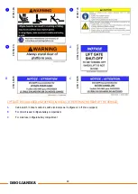
All safety decals have been affixed in conformance with the installation instructions and are clearly legible.
2 - Inspection of the mechanical part
The size, number and spread of mounting bolts conform with the installation instructions. All bolts are fastened to the
prescribed torque values. Check for potential deformation of the mounting bolts and plates after weight testing.
The extension plate, side steps, braces and dock bumpers are installed in conformance with the installation instructions.
All welding has been performed by qualified welders.
All articulation pins and retaining bolts are properly fastened and secured.
All articulation pins are equipped with lube fittings and are lubricated.
Areas of drilling, cutting, grinding, welding etc. are adequately protected against corrosion.
3 - Inspection of the electrical part
Voltage of the lift is compatible with voltage of the vehicle. The batteries & alternator suit the lift capacity, application &
frequency of use.
The cabin switch in the driver’s cabin, and the main battery isolator switch of the external control box (whichever is
applicable) function OK
The main fuse or circuit breaker, the battery and ground cables are fitted correctly and conform to the fitting instructions,
all bolted connections of cables and fuses are properly tightened and secured.
All electrical connections are coated with dielectric grease.
The position of the exterior control box conforms to the fitting instructions.
The power feed to all auxiliary controls is wired into the safety switch on the main external control box (if so equipped).
When the external control box is active, none of the auxiliary control units are activated, and vice versa.
The “hold-to-run” principle works on all control units: any ongoing movement should immediately stop when one of the
corresponding switches is released.
The cables going to the platform (flashing lights, foot controls, …) are properly routed, and cannot be damaged during the
various movements of the lift.
Summary of Contents for DH-LSP
Page 12: ...11 DHOLLANDIA 9 1 2 2 11 3a Bottom view 10 4 4 5 6 7 8 5 8 2 1 3 3a 3 3b 3c 3d 3b 3c 3d 3e 5 9...
Page 22: ...21 DHOLLANDIA Figure 9 4...
Page 43: ...42 DHOLLANDIA Figure 15 1...
Page 44: ...43 DHOLLANDIA...
Page 45: ...44 DHOLLANDIA...
Page 47: ...46 DHOLLANDIA Figure 16 3 Figure 16 2 400mm 400mm 250mm 400mm 400mm 250mm...
Page 49: ...48 DHOLLANDIA EF0583 LM EN EF0565 EN EF0620 EN EF0570 CAP serial nr EF0564 EN EF0581 EN xxxx...

