9
Version 2.1 October 2015
Den Haan Rotterdam
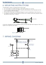
The best way to ensure an optimal performance is that:
• The compressor is mounted straight-up with sufficient space for cooling.
• The compressor needs exactly 24VDC. Keep the wiring between the compressor and the
power supply as short as possible.
• The air horn is mounted on a downward slope (1-2°) with no obstacles in front of the horn.
• The distance between the compressor and the air horn must be as short as possible without
any sharp curves. (max. 10 metre)
If the horn is loosened from the diaphragm casing, its recommended that the nipple of the horn is
taped be fore tightened, see figure.
Tape here
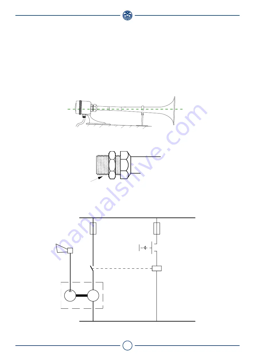
7. WIRING DIAGRAM
Horizontal
M
-
+
Fuse T1A
Relay
Compressor
Push button or
Control panel
Fuse
T60A (DHR compressor)
T20A (Marco compressor)
Air horn
24VDC
Ground
6. MOUNTING INSTRUCTIONS


