background image

4. Read the resistance in the display and then set the function

switch to the lowest W position that is greater than the actual or

any anticipated resistance. The display will indicate the proper

decimal point and value.

CONTINUITY CHECK

1. Set the function switch to the position.

2. Insert the black lead banana plug into the negative (COM) input

terminal Insert the red test lead banana plug into the positive (Ω)

input terminal.

3. Touch the test probe tips to the circuit or wire you wish to check. 

4. If the resistance is less than approximately 30Ω, the audible

signal will sound. If the circuit is open, the display will indicate “1”.

DIODE TEST

1. Insert the black test lead banana plug into the negative 

COM

input terminal and the red test lead banana plug into the positive

diode input terminal.

2. Turn the rotary switch to the    

/ •)))

position.

3. Touch the test probes to the diode under test. Forward voltage

will indicate 400 to 700mV. Reverse voltage will indicate “

I

”.

Shorted devices will indicate near 0mV. Shorted devices will

indicate near 0mV and an open device will indicate “

I

” in both

polarities.

BATTERY TEST

1. Insert the black test lead banana plug into the negative 

COM

input terminal and the red test lead banana plug into the positive

V

input terminal.

WARNING:

To avoid electric shock, never measure continuity on

circuits or wires that have voltage on them.

WARNING:

To avoid electric shock, disconnect the test leads

from any source of voltage before removing the battery cover.

WARNING:

To avoid electric shock, do not operate your meter

until the battery cover is in place and fastened securely.

2. Select the 1.5V or 9V BAT position using the function select

switch.

3. Connect the red test lead to the positive side of the 1.5V or 9V

battery and the black test lead to the negative side of the 1.5V or

9V battery.

4. Read the voltage in the display.

REPLACING THE BATTERIES

1. When the batteries become exhausted or drop below the

operating voltage, “BAT” will appear in the right-hand side of the

LCD display. The batteries should be replaced.

2. Follow instructions for installing batteries. See the Battery

Installation section of this manual.

3. Dispose of the old batteries properly.

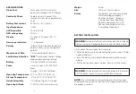
Good

Weak

Bad

9V battery: 

>8.2V

7.2 to 8.2V

<7.2V

1.5V battery: 

>1.35V

1.22 to 1.35V

<1.22V

12

13

Summary of Contents for PL280N

Page 1: ...Instruction Manual PL280N Digital Multimeter PL280N EN 61010 1 CAT III 600V ...

Page 2: ...ion manual to avoid personal injury or damage to the meter NEVER apply voltage or current to themeter that exceeds the specified mamimum Caution Dangerous voltage Danger of electrical shock Continuous double or reinforced insulation complies with IEC536 class 11 Input Limits Function Maximum Input VAC 600V DC AC V DC or V AC 600V DC AC 200Vrms on 200mV range mA DC 200mA 250V fast acting fuse A DC ...

Page 3: ... qualified service technician for calibration and repair CE Symbol of conformity confirms conformity with relevant EU directives The meter complies with EMC directives 89 336 EEC Specifically standards EN 50081 1 and EN 50082 1 as well as the Low Voltage Directive 73 23 EEC described in the standard EN 61010 1 The meter has been designed in accordance with the safety regulations for electronic mea...

Page 4: ... reading This is the accuracy of the measurement circuit digits This is the accuracy of the analogue to digital converter NOTE Accuracy is stated at 65oF to 83oF 18oC to 28oC and less than 75 RH Function Range Resolution Accuracy DC Voltage 200mV 0 1mV 0 5 reading 2 digits V DC 2000mV 1mV 20V 0 01V 200V 0 1V 0 8 reading 600V 1V 2 digits AC Voltage 200V 0 1V 1 2 reading 10 digits V AC 600V 1V 50 60...

Page 5: ...ve Humidity 70 operating 80 storage Operating Altitude 7000ft 2000 meters maximum Weight 255g Size 150mm x 70mm x 48mm Safety For indoor use and in accordance with Overvoltage Category II Pollution Degree 2 Category II includes local level appliance portable equipment etc with transient overvoltages less than Overvoltage Category III BATTERY INSTALLATION 1 Disconnect the test leads from the meter ...

Page 6: ... very dangerous and should be measured with great care CAUTION Do not measure DC voltages if a motor on the circuit is being switched ON or OFF Large voltage surges may occur that can damage the meter DC VOLTAGE MEASUREMENTS 1 Set the function switch to the highest V DC position 2 Insert the black test lead banana plug into the negative COM input terminal Insert the red test lead banana plug into ...

Page 7: ... terminal 4 Remove power from the circuit under test then open up the circuit at the point where you wish to measure current 5 Touch the black test probe tip to the negative side of the circuit Touch the red test probe tip to the positive side of the circuit 6 Apply power to the circuit 7 Read the current in the display For mA DC measurements reset the function switch to successively lower mA DC p...

Page 8: ...mV and an open device will indicate I in both polarities BATTERY TEST 1 Insert the black test lead banana plug into the negative COM input terminal and the red test lead banana plug into the positive V input terminal WARNING To avoid electric shock never measure continuity on circuits or wires that have voltage on them WARNING To avoid electric shock disconnect the test leads from any source of vo...

Page 9: ...se cover WARNING To avoid electric shock do not operate your meter until the fuse cover is in place and fastened securely 24 Month Warranty Di Log instruments are subject to stringent quality controls If in the course of normal daily use a fault occurs we will provide a 24 month warranty only valid with invoice Faults in manufacture and materials defect will be rectified by us free of charge provi...

Reviews: