


1. INTRODUCTION
Thank you for purchasing a DIAMAPRO® SYSTEMS product.
This manual provides information and procedures to safely operate and
maintain the AS-1000 For your own safety and protection from injury,
carefully read, understand, and observe the safety instructions described
in this manual.
Keep this manual or a copy of it with the machine. If you lose this manual
or need an additional copy, please contact DiamaPro Systems®. This
machine is designed and built with user safety in mind; however, it can
present hazards if improperly operated and serviced.
Please follow the operating instructions carefully. If there are any questions
regarding operating or servicing of this machine, please contact
DiamaPro Systems®.
Disclaimer:
DiamaPro Systems® and its affiliates take no responsibility
for any damage, injury or death resulting from the incorrect or unsafe use
of this product. Use of this product should be undertaken by competent
persons only. It is the operator’s responsibility to ensure that the following
safety procedures are followed. If you are unsure, do not operate this
product.
2. GENERAL DESCRIPTION
The AS-1000 is a portable, electrically powered Air Filtration machine,
designed and manufactured by DIAMAPRO SYSTEMS®. The machine’s
function is to filter air and remove suspended airborne particulates.
This unit has a three stage filtering system. The Pre-Filter stage captures
the bulk of the dust and debris. The second stage utilizes a two-ply Ring
Filter that captures any dust and dirt able to penetrate the Pre-Filter. The
final stage is the 99.97% - 0.3 micron HEPA Filter or the 5 micron general
purpose filter. The HEPA filter is utilized in abatement work or areas where
an extremely high level of filtration is desired. The general purpose filter is
utilized when trying to reduce visible air born particulates that are deemed
non hazardous.
The AS-1000 requires a 110/115V - 10 Amp, single phase power source.
DO NOT USE CIRCUITS EXCEEDING SPECIFIED
VOLTAGE. HIGHER VOLTAGE WILL DAMAGE
CONTROLS AND COULD CAUSE SHOCK OR FIRE
HAZARD.
3. ROUTINE MAINTENANCE
Inspect the unit for any loose or damaged parts prior to use.
CAUTION:
Be sure power supply is in the OFF position
prior to inspection!
A.
Clean the surfaces of the unit to remove accumulated dust or dirt. Do
not use petroleum distillates, solvents, or thinners as cleaning agents.
Remove any accumulated dust and dirt from control panel.
B.
Periodic checks should be made of the filter brackets to ensure
thumbscrews and knobs are secure.
C.
Filters should be checked daily and replaced if needed. This will help
ensure proper air flow and extend motor life.
D.
Inspect ALL power connection. Be sure that the recessed plug is secure
to the panel. If recessed plug is not secured, electrical shock or shortage
may occur.
E.
Inspect your power cords connections for breaks, scorched areas,
melting, oxidation, or signs of wear. If cord shows ANY of these signs,
replace.
CAUTION:
Do not tamper with or modify the blower housing, control
panel, drive motor, or wiring scheme. Tampering or modifications
could result in premature wear or failure and will void factory
warranty
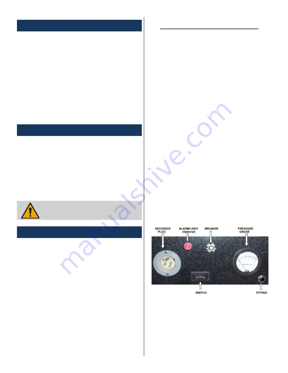
CONTROL DESCRIPTIONS
1. Power Switch
Switch used to turn on your AS-1000. Select either high or low set-
tings depending on the desired volume of air to be filtered.
2. Circuit Breaker
This is attached to the units main power supply to assist in protecting
the blower motor from power surges. The circuit breaker also helps
protect the operator against electrical shock or hazards.
3. Differential Pressure Gauge
This is used to determine filter efficiency. The DPG measures nega
-
tive pressure on the clean side of the filters. As the Filters load with
dust and debris, the negative pressure will increase and move the
needle of the DPG. A new filter will register 1.0-1.2” of water column.
A fully loaded filter will register approximately 1.6”-1.8”” of water
column.
4. Barbed Fitting
Inlet used to measure pressure of surrounding ambient air.
5. Male Recessed Plug
Firmly insert the female end of a proper gauge extension cord to
power the machine.
CAUTION:
A
loose, corroded, ill fitted or damaged extension cord
can cause pre-mature failure and void your warranty.
6. Audible Alarm - (Optional Feature)
Audibly alerts the operator when filters are loaded or when air flow is
greatly decreased. The alarm will sound once the pressure gauge
reaches 1.6”-1.8” of water column.
7. Visual Light - (Optional Feature)
Visually alerts the operator when filters are loaded or when air flow
is greatly decreased. The alarm will light once the pressure gauge
reaches 1.6”-1.8” of water column
AS-1000 CONTROL PANEL
Summary of Contents for AS-1000
Page 5: ...6 WIRING DIAGRAM ...
Page 6: ...6 PARTS BREAKDOWN ...


