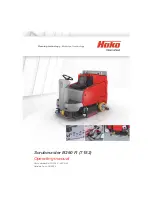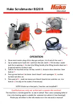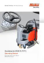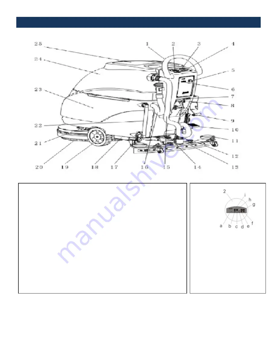
DIAGRAMS OF THE MACHINE
1. Handlebar
2. Control Panel
3.
Suction Motor Button (b)
4.
Brush Motor Button (c)
5. Power Switch
6. Timer
7. Socket for Charger
8.
Squeegee Height Adjusting Handle
9. Manual Pressurized Handle
10. Brush Pedal
11. Guard Wheel
12.
Fixed Handle of Squeegee
13. Squeegee
14. Regulating Handle of Squeegee
15. Water Suction Pipe
16. Water Drain Out Pipe
17. Water Valve
18. Metal Frame
19. Wheel
20. Brush
21. Clean Water Filtration
22. Water Level Indicator
23. Solution Tank
24. Dirty Water Tank
25. Dirty Water Tank Cover
a. Battery Indicator
b. Suction Motor Button
c. Brush Motor Button
d. Brush Install and Release Button
e. Rate Regulation (slow) Button
f. Rate Regulation (fast) Button
g. Rate Indication
h. Indication of Operation of Brush
Motor
i. Indication of Operation of Suction
Motor


