background image

EXA-PROG 

USB programming adapter for AVR-ISP, AVR-UPDI, STM32, LPC, ESP8266, ESP32 


Page 3 


TESTING FUNCTION 

If you have problems to program an attached microcontroller you can use the following option to check whether there is an 
error in the programming adapter. EXA-PROG contains integrated testing hardware which can be used to check the signal 
level of the programming interface. 

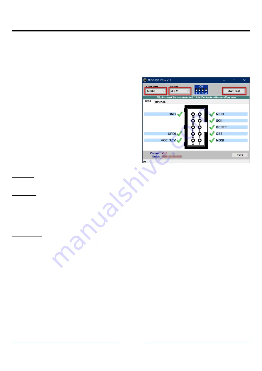
For this please start the EXA-PROG Tool in Windows (file name: Exa_Tool_xxx.exe; xxx = version) which you can find in 
the EXA-PROG program package. 

1. 

Select the tab “TEST”. 

2.  Select the COM port of the EXA-PROG. If you don

’t know ex-

actly  which  COM  port  is  used  by  your  EXA-PROG  you  can 
identify it simply by comparing the COM port list before and 
after plugging the programmers into the PC. 

3.  Select the voltage (power). 
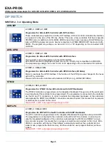
4.  Set the DIP switches on the programmer according to the 

pattern shown.  

5.  Remove  all  wires  from  the  EXA-PROG  programming  con-

nector.  

6.  Push  the  button 

“Start Test“. All ports are now  queried one 

after the other and the signal levels are measured.  

  For  the  test  please  leave  the  programming  port  of  the  pro-

grammer unconnected. There may not be any connections to 
a microcontroller or an external circuit.  

Via the tab “UPDATE” you can also make an update of your EXA-
PROG

’s firmware if this is necessary. 

 
POSITIVE: 

If all signal levels are ok the programming problem is probably located in the connection to the microcontroller or the reason 
is an incorrectly set programming software. 

NEGATIVE: 

In case the test is negative, first check if the right voltage was selected and if the DIP switches on the EXA-PROG agree 
with the switch position which gets displayed. Are there really no external components connected to the programming port? 
Also check the  USB  voltage  with a multimeter by setting DIP switch  1 to ON and measuring the  voltage  between  PIN2 
(plus) and PIN10 (minus) at the programming port. This power level must be between 4.5V and 5.2V.


If, despite all tests and further checks, it turns out that your EXA-PROG is defective please contact the seller you bought it 
from. Please always give the exact error description and perhaps a screenshot of the EXA-PROG tool.  

PREVENTIVE: 

Unfortunately, it happens again and again that the programming adapter gets destroyed throughout experiments with the 
programming of microcontrollers. That also happens to absolute experts which is why they usually have another program-
mer as a reserve so that the current project does not get slowed down. In order to prevent the defect of a programmer you 
should note the following things: 


Always connect the GND line (PIN10 of the programming port) to the circuit first in which there is the microcontroller 
that is to be programmed. So there is a potential equalization between the programmer and the circuit. 


Do not connect output signals on the programming connector (e.g. PIN1, PIN3, PIN5, PIN7) directly to GND or to 
the power supply. The output drivers could get destroyed. 


Make sure that that the pins on the programming connector are not exposed to a higher voltage than the voltage 
set on DIP switch 1.  


Summary of Contents for EXA-PROG

Page 1: ...ate adjustment in the AVR ISP mode Clock generator for AVR controller with wrong fused oscillator Button for reset of the connected microcontroller 10 pin standard ISP port Optional equipment 10 pin to 6 pin adapter ESP01 adapter Mini USB port for power supply and connection to PC Firmware updateable via USB Windows PC tool for testing the signal levels at the programming port Techncal Data Curren...

Page 2: ...amming tools of the manufacturers or to freely available tools In its delivery condition EXA PROG is set to the mode AVR ISP with 3 3V all DIP switches to OFF In the AVR ISP mode EXA PROG is compatible to STK500 and works with AVR ATMEL MICROCHIP Studio as well as AVRDUDE Arduino Bascom Notice With Windows 10 or 11 please only use ATMEL MICROCHIP Studio 7 x or higher Older versions do not work In ...

Page 3: ...correctly set programming software NEGATIVE In case the test is negative first check if the right voltage was selected and if the DIP switches on the EXA PROG agree with the switch position which gets displayed Are there really no external components connected to the programming port Also check the USB voltage with a multimeter by setting DIP switch 1 to ON and measuring the voltage between PIN2 p...

Page 4: ...N3 BOOT is set to the HIGH level a 50ms long reset pulse is generated and then PIN3 BOOT goes back to LOW The green LED flickers briefly as an indicator that the reset was triggered NXP LPC A short button press less than a second triggers a RESET of the connected controller After releasing the button a 50ms long LOW pulse is generated at PIN5 RESET PIN3 BOOT remains on HIGH A long button press lon...

Page 5: ...es with ATTiny controllers Please don t use with controllers with dedicated UPDI pin e g AVR32 64 128DA STM32 2 ON 3 OFF 4 OFF Programmer for STM32 Cortex M Controller with UART Bootloader The STM32 controller is programmed via the integrated bootloader through one of the serial ports see data sheet of the controller to be programmed The programmer is connected to the controller via the RX and TX ...

Page 6: ...m voltage of approx 5V Please note that the exact voltage value may vary and depends on the voltage at the USB port This value can fluctuate depending on the load and it can be between 4 5V and 5 2V However this is usually negligible when microcontrollers are being programmed Notices The maximum load on the programming port is 500mA at 5 volts and 300mA at 3 3 volts If more power is required pleas...

Page 7: ...oes not respond anyway please check the line connections first MISO to MISO and MOSI to MOSI that gets confused very often SCK to SCK and RESET to RESET Are there no other components connected to the programming lines Any capacitor present on the RESET pin must be removed Does the connected microcontroller have a power supply The AVR controller may be missing the system clock because the fuses are...

Page 8: ... the controller is reactivated for programming via a short 12 volt pulse If the controller is to be programmed in a circuit make sure that there may not be any components on the UPDI pin Please do not use this mode for controllers with dedicated UPDI pin e g AVR32 64 128DA NOTICES TIPS Connect only PIN2 to the circuit to be programmed if it does not have its own power supply and if the expected po...

Page 9: ... STM32 it must be supplied with 3 3 volts If the power consumption is no higher than 300mA the controller including the circuit can also be supplied by the EXA PROG Programming does not need a crystal connected to the STM32 The bootloader of the STM32 uses the internal RC oscillator HSI clock to generate the system clock Unfortunately the BOOT0 and RESET lines cannot be controlled with the program...

Page 10: ...T lines works very well with the tool Flash Magic If you develop your own programming tool the BOOT and RESET lines can be controlled via the DTR BOOT and RTS RESET signals This can also be done manually using the reset button on the EXA PROG This programmer does not support 8 bit controllers LPC9xx and NXP controllers without an ARM Cortex core EXA PROG as USB Serial Converter EXA PROG can be use...

Page 11: ...am the ESP8266 or ESP32 it must be supplied with 3 3 volts If the current consumption is not higher than 300mA then the controller including the circuitry can also be supplied from the EXA PROG When using ESPTOOL the control lines GPIO0 and RESET are activated automatically A manual activation of the bootloader is therefore not necessary However activation can also be triggered using the reset but...

Page 12: ...OG The English version of this manual is a translation For legal issues the authoritative version of these instructions is the German one LINKS LED Genial shop http www led genial de Diamex shop http www diamex de Download AVR ATMEL MICROCHIP Studio http www mikrocontroller net articles Atmel_Studio UPDI programming with AVRDUDE https github com ElTangas jtag2updi using with avrdude ESPTOOL for ES...

Page 13: ...EXA PROG USB programming adapter for AVR ISP AVR UPDI STM32 LPC ESP8266 ESP32 Page 13 ...

Reviews: