background image


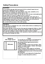
Safety Precautions 


WARNING 

1) To prevent damage which may result in fire or shock hazard, do not 
expose this appliance to rain or moisture. 
Do not place containers with water (flower vase, cups, cosmetics, etc.) 
above the set. ( including on shelves above, etc.) 
2) To prevent electric shock, do not remove cover. No user serviceable parts 
inside. Refer servicing to qualified service personnel. 
3) Do not remove the earthing pin on the power plug. This apparatus is 
equipped with a three pin earthing-type power plug. This plug will only fit an 
earthing-type power outlet. This is a safety feature. If you are unable to 
insert the plug into the outlet, contact an electrician. 
Do not defeat the purpose of the earthing plug. 


CAUTION


This appliance is intended for use in environments which are relatively free 
of electromagnetic fields. 
Using this appliance near sources of strong electromagnetic fields or where 
electrical noise may overlap with the input signals could cause the picture 
and sound to wobble or cause interference such as noise to appear. 
To avoid the possibility of harm to this appliance, keep it away from sources 
of strong electromagnetic fields. 


Symptoms 

After-images appear 

Check 

Do not allow a still picture to be displayed for 
an extended period, as this can cause a 
permanent after-image to remain on the 
Plasma 

Display

Examples of still pictures include logos, video 
games, computer images, Teletext and images 
displayed in 4:3 mode. 
Note: 

P

ermanent after-image on the Plasma 

Display

 resulting from fixed image use is not an 

operating defect and as such is not covered by 
the Warranty. 
This product is not designed to display fixed 
images for extended periods of time. 


Welcome 


1

Summary of Contents for DV42P2

Page 1: ...roperly Keep this manual in a safe place Notes on lnstallation This product is marketed with the assumption that it is to be installed by qualified personnel with relevant skills and competence It is...

Page 2: ...tion of Video Signal DVD VCD VCR Input Connection of PC Signal PC DVI D Output Connection of Video Signal Operation Operation of Remote Control Menu Function Main Menu Picture Menu Sound Menu Setup Me...

Page 3: ...for use in environments which are relatively free of electromagnetic fields Using this appliance near sources of strong electromagnetic fields or where electrical noise may overlap with the input sign...

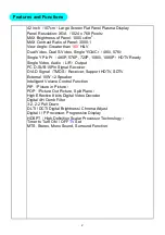
Page 4: ...dy Single Video Audio L R Output PC D SUB 15Pin Signal Receiver DVI D Signal TMDS Receiver Support HDTV SDTV External 10W 2 Speaker Intelligent Volume Control Function PIP Picture in Picture POP Pictu...

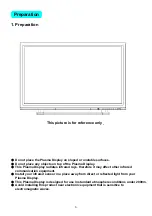
Page 5: ...sma Display radiates infrared rays therefore it may affect other infrared communication equipment Install your infrared sensor in a place away from direct or reflected light from your Plasma Display T...

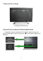
Page 6: ...nce only Connect the AC cord plug to the Plasma Display Panel Connect the AC power cord plug to the AC IN jack Connect the other side plug to the Wall Outlet Press the Power switch on the Plasma Displ...

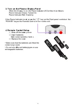
Page 7: ...ndicator is red press the key on the Front panel controls or the POWER key on the Remote Control to turn on the unit 4 Remote Control Setup Slide off the battery cover Insert batteries Note correct po...

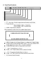
Page 8: ...vailable Signal Inputs S VIDEO2 AV2 YCbCr D SUB AV1 S VIDEO1 YPbPr DVI MENU Displays the On Screen Display to configure the Plasma Display Press this key to open the Main Menu press CH key select an i...

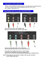
Page 9: ...2 Component inputs Y Cb Cr and Y Pb Pr Each Component source has its own set of R L audio inputs If your DVD or Set Top Box has Y Cb Cr or Y Pb Pr outputs connect it to the appropriate component inpu...

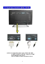
Page 10: ...D PC INPUT D SUB AUDIO DVI INPUT DVI D AUDIO Notice The highest Resolution input is 1280 X 1024 60Hz If a higher resolution is selected signal out of range will be displayed on the screen 8 Some PC mo...

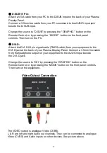
Page 11: ...gnal cable TMDS cable from your equipment to the DVI D jack at the back of your Plasma Display Panel Connect a 3 5mm line cable from the headphone output on your equipment to the AUDIO input beside th...

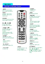
Page 12: ...n the Menu VOL VOL Volume adjustment or adjust item in Menu W SELECT Select Main picture PIP P MODE Select Picture Mode Normal User Movie Bright 0 9 number Number key CHRTN TV channel return see last...

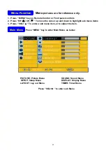
Page 13: ...H CH To move the cursor up and down to highlight sub menu items 3 Press VOL To enter a sub menu item or to adjust the item Main Menu Press MENU key to enter Main Menu as below PICTURE Picture Menu SOU...

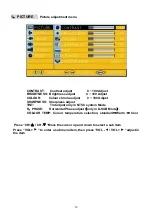
Page 14: ...djust 0 100 Adjust SHARPNESS Sharpness adjust TINT Tint adjust only in NTSC system Mode H PHASE Horizontal Phase adjust only in D SUB Mode COLOUR TEMP Colour temperature selection standard Warm Cool P...

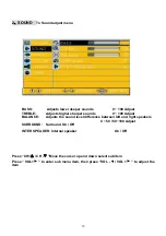
Page 15: ...ounds 0 100 Adjust BALANCE Adjusts the sound level difference between left and right speakers 0 50 50 100 Adjust SURROUND Surround On Off INTER SPEAKER Internal speaker On Off Press CH CH Move the cur...

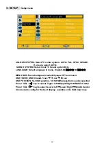
Page 16: ...in menu English MENU BKG Menu background select Opaque Translucent OSD TIMER OSD timeout 5 sec 15 sec 60 sec OSD POSITION Set OSD position 5 OSD MENU positions can be selected Press VOL key to select...

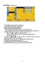
Page 17: ...en during adjustment PAN AND ZOOM Press VOL to enter the zoom menu Press CH CH to adjust zoom level When scale is set larger than 1x press the DISPLAY INFOR key to enter pan function Press the CH CH o...

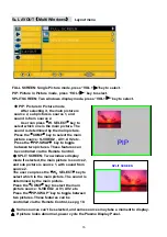
Page 18: ...the PIP SWAP key to toggle between two pictures These features can be controlled via the Remote Control Transmitter see page 10 SPLIT SCREEN Two windows display mode If selected the main picture is s...

Page 19: ...first POWER SAVING TIMER If no signal input is detected the Panel will enter standby Power saving timer options 5Min 10Min 15Min 20Min 25Min 30Min All time settings are configured as above POWER ON CH...

Page 20: ...k Do not remove the cover or modify it in any way High voltage which can cause severe electric shocks are present inside the Plasma Display For any inspection adjustment and repair work please contact...

Page 21: ...may affect other infrared communication equipment Install your infrared sensor in a place away from direct or reflected light from Plasma Display Cleaning and maintenance The front of the display pan...

Page 22: ...Specification Item Specification 933 532 Panel Spec Power input sources 100 240V 50 60Hz Power consumption 420W Typical 20...

Page 23: ...o AV mode Not plugged into A C outlet Not switched on Picture Sound controls set at minimum levels Check if in stand by mode No Colour Normal Sound Colour Controls set at minimum levels Weak or Poor o...

Page 24: ...h Wales and Australian Capital Territory 348 Victoria Road Rydalmere NSW 2116 Telephone 02 1300 651 808 Fax 02 9684 7684 Queensland Unit 12 469 Nudgee Road Hendra QLD 4011 Airlink Business Park Teleph...

Reviews: