background image


18


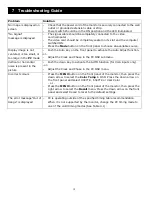
Problem


Solution


No image is displayed on 
screen 

–  Check that the power cord of the monitor is securely connected to the wall 

outlet or grounded extension cable or strip. 

–  Power switch should be in the ON position and the LED illuminated. 

“No Signal” 
message is displayed 

–  The signal cable should be completely connected to the video 

card/computer. 

– 

The video card should be completely seated in its slot and the computer 

switched ON. 

– 

Press the 

Mode

 button on the front panel to choose an available source. 

Display image is not 
centered, is too small, or 
too large in the 

PC 

mode 

–  Push the Auto key on the front panel to activate the Auto Adjust function. 

-or- 

–  Adjust the Clock and Phase in the PC OSD submenu. 

Vertical or horizontal 
noise is present in the 
picture 

–  Push the down key to activate the AUTO function (for VGA inputs only). 
-or- 
–  Adjust the Clock and Phase in the PC OSD menu. 

Incorrect colours 

–  Press the 

MENU 

button on the front panel of the monitor, then press the 

down arrow to select the 

Color Temp 

in OSD. Press the down arrow on 

the front panel and select 9300°K , 6500°K or User Color 
- or - 

– Press 

the 

MENU 

button on the front panel of the monitor, then press the 

right arrow to select the 

Recall 

menu. Press the down arrow on the front 

panel and select Recall to reset to the default settings. 


The error message “Out of 
Range” is displayed 

–  PC is operating outside of the specified timing table recommendation. 

When it is not supported by the monitor, change the PC timing mode to 
one of the valid timing modes (See Table 4.1). 

7  Troubleshooting Guide

Summary of Contents for DX-D193P

Page 1: ...DIAMOND DIGITAL DX D193P Colour TFT LCD Monitor 19 43 cm LCD Panel Size...

Page 2: ...t of this publication may be reproduced transmitted transcribed stored in a retrieval system or translated into any language or computer language in any form or by any means electronic mechanical magn...

Page 3: ...5 3 Connecting the Composite Video to the Monitor 10 5 4 Connecting the Y C S Video Signal to the Monitor 11 5 5 Connecting the YPbPr Signal to the Monitor 11 5 6 Connecting Audio to the Monitor 11 6...

Page 4: ...cluding amplifiers that produce heat 8 Protect the power cord from being walked on or pinched particularly at plugs convenience receptacles and the point where they exit from the apparatus 9 Only use...

Page 5: ...2M plug type optional 2 3 Precautions HANDLING The monitor must be treated with caution and not be exposed to impact and shock The monitor has a fragile glass screen Never rub it with a hard stiff ob...

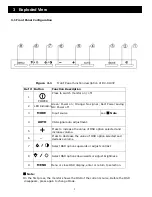
Page 6: ...ee Note 4 AUTO VGA signal auto adjustment 5 Press to increase the value of OSD option selected and increase volume 6 Press to decrease the value of OSD option selected and decrease volume 7 Select OSD...

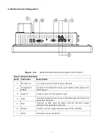
Page 7: ...2 Component YPbPr Connect to component input such as the video output of a DVD player 3 Audio In Audio source for Component input 4 VGA Connect to R G B input such as the VGA output terminal of a per...

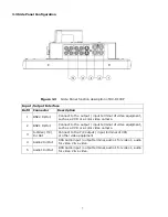
Page 8: ...R or a color video camera 2 BNC1 In Out deo equipment Connect to the output input terminal of vi such as a VCR or a color video camera 3 S Video Y C In Out Connect to the Y C output input terminal of...

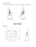
Page 9: ...8 3 4 Tilt Swivel Angle The viewing angle of the monitor can be adjusted to the most comfortable monitoring status Min Degree Max Degree 5 degree 40 degree 3 5 Dimension...

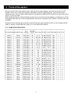
Page 10: ...terlace H Pol V Pol Mode 1 VESA 640x350 85 31 5 37 861 85 08 NO Mode 2 Us Text 720x400 70 28 322 31 469 70 087 NO Mode 3 VESA 640x400 85 31 5 37 861 85 08 NO Mode 4 VESA 720x400 85 35 5 37 927 85 039...

Page 11: ...on the rear of the monitor see Figure The monitor automatically adjusts to either power input voltage The viewing angle of the LCD can be adjusted for the most comfortable monitoring status 5 3 Conne...

Page 12: ...rs with same colors green blue red 5 6 Connecting Audio to the Monitor There are 3 sets of stereo audio connectors and 1 stereo mini jack for audio input located on the rear side panel see Figure 3 2...

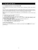
Page 13: ...D menus use the MENU button to select a menu or exit a menu To navigate the set up menus follow the steps below 1 Connect the CVBS or VGA cable 2 Press the POWER button to turn on the unit see Figure...

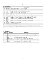
Page 14: ...13 6 2 1 VGA DVI Signal OSD Menu Main Menu Sub Menu _ PIP POP Above Value data is for reference only Change without notice...

Page 15: ...of the screen image range 0 100 11 OSD H Pos Adjust the left or right position of the OSD range 0 100 12 OSD V Pos Adjust the up or down position of the OSD range 0 100 13 Volume Adjust the volume co...

Page 16: ...15 6 2 3 Video Composite YPbPr S Video Signal OSD Menu Main Menu Sub Menu Above value data is for reference only Change without notice...

Page 17: ...tion of the OSD range 0 100 9 OSD V Pos Adjust the up or down position of the OSD range 0 100 10 Volume Adjust the volume control 11 PIP POP Entering PIP POP submenu 12 Language Select languages Engli...

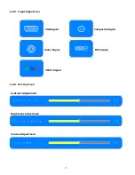
Page 18: ...17 6 2 5 Input Signal Icon VGA Signal Composite Signal S Video Signal DVI Signal YPbPr Signal 6 2 6 Hot Key Icon Contrast Adjustment Brightness Adjustment Volume Adjustment...

Page 19: ...d Phase in the PC OSD submenu Vertical or horizontal noise is present in the picture Push the down key to activate the AUTO function for VGA inputs only or Adjust the Clock and Phase in the PC OSD men...

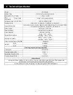
Page 20: ...A Rated Voltage 100 240 VAC 50 60 Hz Power Output DC 12V 500mA Operating Condition Temp 0 C 40 C Humidity 20 80 Storage Condition Temp 20 C 60 C Humidity 15 85 Power Consumption On Off 45W 5W Weight N...

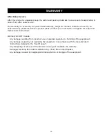
Page 21: ...ocal dealer or supplier for repair and maintenance instructions Warranty Do NOT Include Any damage resulting from incorrect use or careless operation or handling of the equipment Any damage caused by...

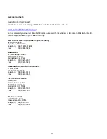
Page 22: ...Capital Territory 348 Victoria Road Rydalmere NSW 2116 Telephone 02 1300 651 808 Fax 02 9684 7684 Queensland 12 468 Nudgee Road Hendra QLD 4011 Airlink Business Park Telephone 07 3623 2000 Fax 07 363...

Reviews: