background image

 KNIVES


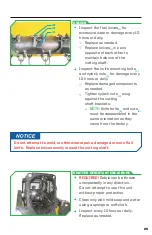
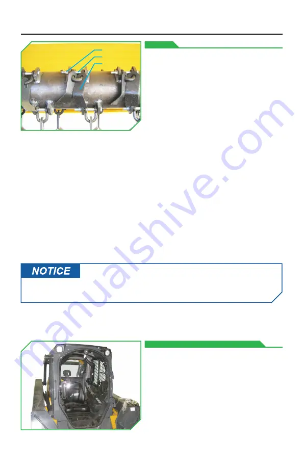
Inspect the flail knives

(1)

 for 

excessive wear or damage every 10 
hours or daily.  


Replace as needed.


Replace knives

(1)

 in pairs 

opposite of each other to 
maintain balance of the  
cutting shaft.


Inspect the knife mounting bolts

(2)


and nylock nuts

(3)

 for damage every 

10 hours or daily.  


Replace damaged components 
as needed. 


Tighten nylock nuts

(3)

 snug 

against the cutting  
shaft brackets.  


-

NOTE:

 Knife bolts

(2)

 and nuts

(3)


must be reassembled in the 
same orientation as they 
came from the factory. 

 SHATTER RESISTANT ENCLOSURE


REQUIRED!

 Debris can be thrown 

unexpectedly in any direction.  
Do not attempt to use this unit 
without proper protection. 


Clean only with mild soap and water 
using a sponge or soft cloth. 


Inspect every 10 hours or daily. 
Replace as needed.

Do not attempt to weld, or otherwise repair a damaged or worn flail 
knife.  Replace knives evenly around the cutting shaft. 

(3)
(2)
(1)

25

Summary of Contents for FLAIL MOWER

Page 1: ...DIAMONDMOWERS COM DIAMONDMOWERS COM OPERATOR S MANUAL OPERATOR S MANUAL SKID STEER COMPACT TRACK LOADER FLAIL MOWER...

Page 2: ...nd and follow the instructions found in this operator s manual could lead to serious injury Operators who choose to operate this equipment without following instructions or who choose to operate this...

Page 3: ...r That also means being there when you need us CONTACT US Parts 888 960 0361 parts diamondmowers com Warranty Service 888 960 0364 warranty diamondmowers com Main Office 800 658 5561 605 977 3300 Webs...

Page 4: ...ntly so you can get back to work fast TRANSFERRED OWNERSHIP If you have acquired this Flail Mower from a previous owner we encourage you to register your equipment online By registering your Diamond M...

Page 5: ...INTENDED USE 6 TAKE A LOOK AROUND 7 GETTING STARTED 8 OPERATING YOUR FLAIL MOWER 10 MAINTENANCE 16 TROUBLESHOOTING 27 PARTS BOOK 29 INDEX 39 TABLE OF CONTENTS...

Page 6: ...This attachment should only be used in an area free of obstructions and bystanders Any use on non vegetative material or in an area that is not clear of persons and property is strictly prohibited Any...

Page 7: ...tensioner no manual adjustment needed HYDRAULIC MOTOR Flail mowers equipped with a high flow high efficiency hydraulic motor matched to your skid steer compact track loader HOSES Shipped with quick c...

Page 8: ...teer compact track loaders Clean connections before attaching to prevent contamination The Flail Mower will mount onto the front of the skid steer compact track loader quick attach plate in place of a...

Page 9: ...long that the hose can pinch Start machine at low idle and verify that the cutting shaft is spinning in Reverse rotation NOTE Forward rotation is defined as blade rotation the same as the skid steer...

Page 10: ...IOUS injury or death WILL result if instructions are not followed Indicates where SERIOUS injury or death COULD result if instructions are not followed Indicates where MINOR injury COULD result if ins...

Page 11: ...as come to a complete stop before exiting the cab When transporting Diamond s Flail Mower between operations make sure to protect it from collisions and accidental damages by placing it in the stowed...

Page 12: ...ispersed If you hear the cutting shaft or engine slow down lift up the head and or slow your ground speed A second pass may be needed for heavy brush or grass Complete the initial pass at 12 305mm int...

Page 13: ...FINISHED MOW Use for a finished look Drive straight into the material keeping the deck low and level or slightly pitched forward Maintain speed of the cutting shaft and ground speed 13...

Page 14: ...ive straight into the material Allow enough time for the tree section to fall away while cutting Use a smooth quick action to cut the material completely NOTE Never drop the mower straight down on tre...

Page 15: ...ing Damage will incur to the cutting shaft and bearings as a result of driving down pancaking on top of the material Dropping the Flail Mower straight down pancaking on heavy vegetation can cause seve...

Page 16: ...500 HOURS ANNUALLY AS NEEDED BELTS PULLEYS Adjust CUTTING SHAFT Grease Inspect DISCHARGE FLAP Inspect GROUND ROLLER Oil HYDRAULIC FITTINGS Inspect KNIVES Inspect SHATTER RESISTANT ENCLOSURE Inspect C...

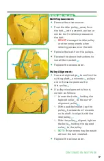
Page 17: ...ignment Use a straight edge 5 to confirm the cutting shaft 3 and motor 4 pulleys are in the same plane as the idler pulley 1 If pulley misalignment is found correct as follows Loosen the bolts 6 holdi...

Page 18: ...will be exposed Re attach the main center bolt to lock it into position Replace the belt 2 as illustrated dashed outline and access cover Disconnect the pressure 9 and return 10 hoses from the skid s...

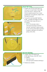
Page 19: ...e the cutting shaft bearing bolts 2 to 90ft lbs 122Nm on each side of the flail every 50 hours or weekly NOTE The access covers covering the pulleys and belt must be removed to gain access to the cutt...

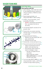
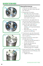
Page 20: ...a new O ring Rest the ground roller 2 on the ground Block it from moving Unbolt 3 the ground roller 2 from each side of the flail DO NOT reassemble the hardware from one side of the flail on the other...

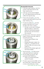
Page 21: ...castle nut whichever exposes the hole first until the hole is fully exposed Liftthe ground roller insert and pull down on the ground roller shaft to check for end play 4 No end play proceed to the nex...

Page 22: ...ace where the insert will mate to 4 Place a dot of RTV silicone sealant 12 on the groove between each hole Place the O ring 13 into the groove on the end cap Place the end cap onto the ground insert w...

Page 23: ...on the center bolt 16 for the non drive belt side Use loctite 262 with primer 7649 on the 4 outer bolts 3 for the non drive belt side Torque all 5 bolts 3 16 on the non drive belt side to 75ft lbs 10...

Page 24: ...serious health risks HYDRAULIC HOSES FITTINGS Hydraulic hoses and fittings should be inspected every 10 hours or daily What to look for Hydraulic fitting clamps and threaded connections for any hydrau...

Page 25: ...s 3 snug against the cutting shaft brackets NOTE Knife bolts 2 and nuts 3 must be reassembled in the same orientation as they came from the factory SHATTER RESISTANT ENCLOSURE REQUIRED Debris can be t...

Page 26: ...and replace hardware at recommended intervals will cause damage to the machine and attachment MAINTENANCE Inspect the skid shoes 1 for excessive wear or damage every 50 hours or weekly Replace as need...

Page 27: ...lail mowers are equipped with automatic self tensioners call Diamond Mowers for assistance Misaligned pulleys Correct pulley alignment PROBLEM POTENTIAL CAUSE SOLUTION Mower Will Not Start or Run No h...

Page 28: ...ensioners call Diamond Mowers for assistance Hydraulic hoses are reversed Verify hydraulic hoses are installed correctly Verify skid steer high flow hydraulics are engaged PROBLEM POTENTIAL CAUSE SOLU...

Page 29: ...PARTS BOOK 29...

Page 30: ...1 2 13 X 1 1 8 GR 8 HEX CAP SCREW 5 11 2154 24 75 FLAP 1 18 0011 25 GREASE ZERK HOSE 1 21 0002 REF PARTS DESCRIPTION REQ PART 26 1 8 GREASE ZERK 2 23 0003 27 75 SKID STEER FLAIL BONNET 1 25 0131 28 GR...

Page 31: ...1 23 1 2 13 X 1 1 8 GR 8 HEX CAPSCREW 5 11 2154 24 90 FLAP 1 18 0014 25 GREASE ZERK HOSE 1 21 0002 REF PARTS DESCRIPTION REQ PART 26 1 8 GREASE ZERK 2 23 0003 27 90 SKID LOADER FLAIL BONNET 1 25 0126...

Page 32: ...23 CLEVIS 56 11 1501 24 1 2 13 X 1 1 8 GR 8 HEX CAPSCREW 5 11 2154 25 102 FLAP 1 18 0012 REF PARTS DESCRIPTION REQ PART 26 GREASE ZERK HOSE 1 21 0002 27 1 8 GREASE ZERK 2 23 0003 28 102 SKID LOADER F...

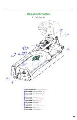
Page 33: ...DECAL IDENTIFICATION All Flail Heads 33...

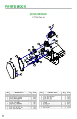
Page 34: ...1 11 0031 10 3 8 X 1 NC HEX CAPSCREW 4 11 0532 11 1 2 X 1 3 4 NC HEX CAPSCREW 4 11 0535 12 5 8 X 3 NC HEX CAPSCREW 1 11 0558 REF PARTS DESCRIPTION REQ PART 13 12MM X 40MM X 1 75 HEX CAPSCREW 1 11 067...

Page 35: ...COUPLER FLAT FACE 1 21 1562 11 5 8 MALE QUICK COUPLER FLAT FACE 1 21 1574 12 5 8 FEMALE QUICK COUPLER FLAT FACE 1 21 1575 REF PARTS DESCRIPTION REQ PART 13 3 4 MALE QUICK COUPLER FLAT FACE 1 21 1576 1...

Page 36: ...OUPLER FLAT FACE 1 21 1562 11 5 8 MALE QUICK COUPLER FLAT FACE 1 21 1574 12 5 8 FEMALE QUICK COUPLER FLAT FACE 1 21 1575 REF PARTS DESCRIPTION REQ PART 13 3 4 MALE QUICK COUPLER FLAT FACE 1 21 1576 14...

Page 37: ...EAL KIT SEAL KIT integral shaft only comes w 30 1162 1 30 1207 REF PARTS DESCRIPTION REQ PART SEAL KIT continental shaft only 1 30 1211 15 SHAFT SEAL CONTINENTAL SHAFT ONLY 300 PSI included in M350 se...

Page 38: ...UST WASHER 2 00 OD X 1 26 ID 5 11 2074 1 CASTLE NUT 6 21 1136 1 1 8 NPT PLUG 7 24 0273 1 O RING 2 7 8 OD 8 33 0031 1 SEAL TCM 132713TC 9 41 1776 1 ASSY GROUND ROLLER SHAFT 10 90 7045 1 GROUND ROLLER I...

Page 39: ...fety Tips 10 Stowed Position 11 Techniques Finished Mow 13 Grass Brush Cut 12 No Pancaking 15 Tree Cut 14 Owner Registration 4 P Parts Book 29 75 1905mm Cutter 30 90 2286mm Cutter 31 102 2591mm Cutter...

Page 40: ...DIAMONDMOWERS COM DIAMONDMOWERS COM 15 1101 DLF MANUAL...

Reviews: