OPERATING
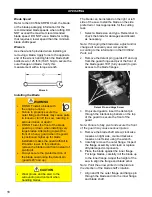
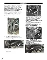
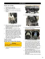
Transmission Lever
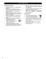
Engaging the Transmission
1. Place the speed control lever at
STOP
.
2. Start the engine.
3. Remove the transmission engagement
lever from the
DISENGAGE
slot.
4. Push the lever up and place it into the
ENGAGE
slot.
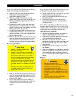
Disengaging the Transmission
1. Place the speed control lever at
STOP
.
2. Remove the transmission engagement
lever from the
ENGAGE
slot.
3. Pull the lever down and place it into the
DISENGAGE
slot.
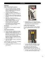
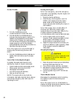
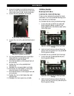
Speed Control Lever
The speed control lever moves the saw
forward and backward at up to 200 ft/min.
Note: The engine must be running at half
throttle or greater to move the saw using the
speed control lever.
Speed Control Lever
1. Slowly push the lever toward
FORWARD
to
move the saw forward and release when at
the desired traveling speed.
2. Slowly pull the lever toward
REVERSE
to
move the saw backward and release when
at the desired traveling speed.
3. Place the lever at
STOP
to stop the saw.
DO NOT assume at any time that the
STOP position will act as a brake.
Note: Always start the engine with the speed
control lever at STOP.
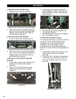
Water Supply
The water supply cools the blade and
minimizes dust when cutting. There are two
blade guard hose connections on the saw, one
on the right side and one on the left. These
connections have water cutout valves to start
and stop the flow of water to the blades. The
left side also has the water source hose
connection upstream of the water cutout valve.
Note: Always test the water supply for
adequate pressure and flow prior to cutting.
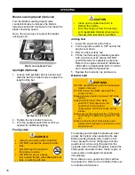
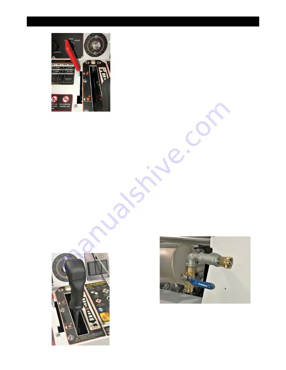
Using the Water Supply
1. Connect the water source hose to the
water source hose connection on the left
side of the saw.
2.
Connect blade guard water hose to the
water valve fitting on the left side of the
saw, or to the single water valve fitting on
the right side of the saw depending on the
side being used for cutting.
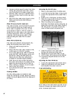
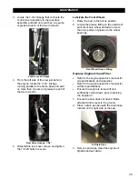
Water Valve on Left Side of Saw with Water
Source Connection
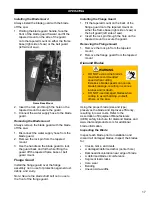
3. Connect the other end of the water supply
hose to the blade guard.
4. Begin the flow of water from the source to
the saw.
5. Just before cutting, open the water valve
lever to begin water flow to the blade.
21
Summary of Contents for CC3538JK Series
Page 1: ...CORE CUT OPERATOR S MANUAL CC3538JK Electronic Fuel Injection May 2020 Rev 20 00 Part 1802723...
Page 2: ......
Page 47: ...REFERENCES 47...
Page 48: ...REFERENCES 48...
Page 49: ...REFERENCES 49...
Page 51: ...REFERENCES...


