background image


OPERATING 

Helpful Hints Prior to Cutting 

Keep the following in mind for better efficiency 
while cutting: 

  Use just enough handle pressure to guide 

the saw down the cutting line. DO NOT 
forcibly direct (twist) the saw from side to 
side when cutting. DO NOT jam, cock, or 
wedge the blade in a cut. 

  Moving too quickly when cutting may stall 

the saw or may cause the blade to climb 
out from the cut. If the saw stalls while 
cutting, put the saw in STOP and raise the 
blade from the cut to restart the engine. 

  Avoid sawing excessively deep to preserve 

the blade and reduce sawing costs. 

  DO NOT lower the blade too quickly or 

move the saw forward too quickly when 
finishing a partial cut to avoid forcing the 
blade into the concrete. 

  Always have a proper water flow when 

cutting for maximum blade efficiency. Using 
too much water when cutting will make the 
slurry look clear. Not using enough water 
will make the slurry look thick and pasty. 

  Refer to the Diamond Products’ Guide for 

Professional Concrete Cutters for 
additional cutting tips and information. 

Tasks Prior to Cutting 

Complete the following tasks prior to cutting: 

  Align the cutting guide(s) with the blade. 

  Clearly mark the cutting line. 

  Turn off all electricity, gas, and water 

around the direct work area. 

Making a Cut 

1.  Align the blade and cutting guide(s) with 

the cutting line. 

2.  Turn on the water and adjust the water 

flow. 

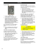
3.  Turn on the 

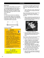
Water Pressure

 switch 

(Optional). 

4.  Turn on the 

Water Pump

 switch if needed. 

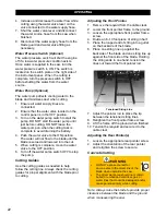
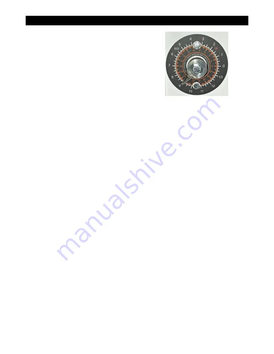
5.  Lower the blade to just above the cutting 

surface and set the cutting depth indicator 
at zero. 


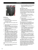
Cutting Depth Indicator 

6.  Slowly lower the blade into the concrete 

surface to a depth of two inches for the 
initial cut. Make the two-inch deep pass 
across the entire cutting line using the most 
efficient blade speed and traveling speed. 
DO NOT cut to the maximum depth in one 
pass.  

Note: Always use the step-cut method when 
cutting for maximum efficiency. For example, 
when cutting to a depth of ten inches, begin 
with a two-inch deep pass, then a four-inch 
deep pass, and finish with another four-inch 
deep pass to complete the cut. 

7.  Raise the blade out of the cut and 

reposition the saw at the end of the cut. DO 
NOT move backwards in a previous cut. 

8.  Starting at the end of the cut, lower the 

blade back into the cut and make another 
two-inch deep pass or a deeper pass 
across the entire cutting line.  

Note: When not using the depth stop, pay 
attention to the cutting depth indicator at all 
times when lowering the blade back into the 
cut or when making a new cut, as the blade will 
not automatically stop at the desired depth. 

9.  Raise the blade out of the cut, reposition 

the saw, and continue the step-cut process 
to reach the maximum depth. DO NOT cut 
any deeper than required. 


23

Summary of Contents for CC3538JK Series

Page 1: ...CORE CUT OPERATOR S MANUAL CC3538JK Electronic Fuel Injection May 2020 Rev 20 00 Part 1802723...

Page 2: ......

Page 3: ...dlebars 15 Control Grip Pushbuttons 15 Blade Lowering Speed Optional 16 Spotlight Optional 16 Fuel System 16 Adding Fuel 16 Blade Guard 16 Installing the Blade Guard 17 Removing the Blade Guard 17 Fla...

Page 4: ...26 Post Cleaning 26 Service Schedule 27 Daily Service 28 Check Engine Oil Level 28 Check Fuel Level 28 Hydraulic System 28 Adding Fluid to the Hydraulic Lift Pump 29 Lubricate the Blade Shaft Bearings...

Page 5: ...39 Tightening the Rear Drive Chain 39 Belt Replacement 40 Replacing the Blade Drive Belts 40 Replacing the Jackshaft Belts 41 Replacing the Transmission Drive Belt 41 Belt Sheaves 41 Changing the Smal...

Page 6: ...n result in serious injuries and or death All operators must be properly trained or supervised by experienced personnel prior to using this saw and should understand the risks and hazards involved Dia...

Page 7: ...to set the cutting depth and increase or decrease the cutting depth 10 Cutting Depth Indicator Displays the current depth of cut in inches 11 Pointer Rope Cleat Secures the front pointer rope 12 Water...

Page 8: ...w Length Max 125 1 2 3188 D Handle Extension Max 28 711 E Frame Length 39 3 4 1010 F Wheel Base Length 18 1 4 464 G Saw Width 30 1 4 768 H Rear Frame Width 23 1 2 597 I Front Wheels Inside Width 20 1...

Page 9: ...ve Engine to Jackshaft 6 V Belts 3VX366 6 V Belts 3VX400 Blade Shaft Drive Jackshaft to Blade Shaft 6 V Belts 3VX400 Blade Coolant Dual stainless steel multi jet spray tubes Blade Guard Attachment Sli...

Page 10: ...umbers in Appendix D Notice The information in this manual may be updated at any time Safety Alerts DANGER Serious injuries and or death will occur if these instructions are not followed WARNING Serio...

Page 11: ...guards and access panels unless stated otherwise prior to operating the equipment Always pivot front of blade guard fully closed to avoid serious injuries DO NOT Assume the equipment will remain still...

Page 12: ...immediately DO NOT expose yourself or anyone else to the direct line of the blade when operating the equipment Always use an appropriate size blade and the correct blade type based on the cutting tas...

Page 13: ...is in the cutting area Ensure the work area is adequately illuminated to ensure safe operation of the machine Hydraulic Safety Turn off the engine prior to servicing hydraulic components Lower the equ...

Page 14: ...ipment in reverse up the ramp Avoid standing directly downhill from the equipment to prevent machine rollover Place the equipment in STOP and turn off the engine once the equipment is loaded in the tr...

Page 15: ...grip and place the first handlebar into the handlebar opening below the handle lock knob The handlebar can fit through two different angled pathways inside the handlebar opening Select the handlebar...

Page 16: ...4 Fill the fuel tank using unleaded gasoline with a minimum of 87 octane DO NOT overfill the tank for expansion purposes Refer to the engine manual for additional information on appropriate fuels in n...

Page 17: ...he Flange Guard 1 Fit the tapered mount on the back of the flange guard onto the tapered mount on either the frame base right side of saw or the belt guard left side of saw 2 Insert the lock pin throu...

Page 18: ...ding environment when handling blades The blade can be installed on the right or left side of the saw Install the blade on the side preferred or most appropriate for the cutting task 1 Select a blade...

Page 19: ...he blade guard 180 fully upward to gain access to the blade 2 On pivoted guards insert the detent pin through the interlocking barrels on the top of the guard to secure the front of the guard Note Fai...

Page 20: ...ne and any saw movement 1 Open the fuel shutoff valve 2 Insert the key into the ignition turn it to START and release when the engine starts Refer to the information in the engine manual when starting...

Page 21: ...time that the STOP position will act as a brake Note Always start the engine with the speed control lever at STOP Water Supply The water supply cools the blade and minimizes dust when cutting There ar...

Page 22: ...to the OFF position 6 Turn off the water pump switch OFF to stop the pump Cutting Guides Use the cutting guides as needed to help follow the cutting line Always check the cutting guides for proper ali...

Page 23: ...Align the blade and cutting guide s with the cutting line 2 Turn on the water and adjust the water flow 3 Turn on the Water Pressure switch Optional 4 Turn on the Water Pump switch if needed 5 Lower t...

Page 24: ...11 Starting at the end of the cut lower the blade back into the cut to the desired depth and turn the Blade Depth Stop knob clockwise until resistance is felt 12 Make another pass across the entire cu...

Page 25: ...sure all equipment and tools required for the maintenance task are staged and available for use Prior to any maintenance being performed know the locations of all safety equipment such as fire extingu...

Page 26: ...ay lubricant when movement becomes stiff and or sluggish Use one to two full pumps of NLGI No 2 premium lithium based grease when lubricating all grease fittings NOTE Use more grease on bearing grease...

Page 27: ...Service Schedule The service schedule is based primarily on the standard operating time of the machine The frequency of the maintenance tasks can be increased based on the working environments of the...

Page 28: ...aw frame is in a level position 1 Visually check the fuel level from the fuel filler cap located on the left side of the control panel 2 If fuel level is low remove the fuel tank fill cap Fuel Tank Fi...

Page 29: ...t overfill as this will cause oil leakage through the breather cap when raising the saw 5 Replace the breather cap and retighten to secure 6 Replace the hydraulic pump cover plate Lubricate the Blade...

Page 30: ...lt manufacturer for additional information on belt tension settings 2 Loosen the four engine mount bolts Engine Mount Bolts Left Side 3 Loosen the nut on both blade drive belt tension bolts Blade Shaf...

Page 31: ...ighten the nut on both blade drive belt tension bolts 13 Retighten the four engine mount bolts 100 Hour Service Bearing Lubrication Lubricate the Jackshaft Bearings There are four jackshaft bearings t...

Page 32: ...ng a 7 16 socket remove the gear guard from the transmission platform weldment Gear Guard 3 Locate the two transmission jackshaft bearing fittings and add no more than two pumps of grease to each of t...

Page 33: ...s 1 Raise the saw to the full up position 2 Locate the grease fitting on the outside of each front axle wheel and add no more than two pumps of grease to the wheel bearings Front Wheel Grease Fitting...

Page 34: ...ations 150 Hour Service Clean the Air Cleaner Filter Element WARNING DO NOT operate the saw without the air filter installed 1 Unhook the retaining clips and remove the end caps Air Filter Assembly 2...

Page 35: ...clamp 8 Open the fuel shutoff valve 300 Hour Service Replace the Air Cleaner Filter Elements WARNING DO NOT operate the saw without the air filter installed 1 Unhook the retaining clips and remove the...

Page 36: ...er s specifications 5 Reinstall the plug wire ensuring that it is fully seated onto the plug 6 Repeat steps 1 through 5 for the second plug Regular Maintenance Drive Alignment Adjust the rear axle whe...

Page 37: ...heel from the rear axle 4 Place a new wheel onto the rear axle 5 Replace the wheel mount washer and retighten the three screws to secure the wheel 6 Repeat steps 2 through 5 for the second rear wheel...

Page 38: ...nkage Adjust the speed control lever linkage when it is set incorrectly for example when the saw is in neutral but the lever is closer to the forward or reverse position 1 Start the engine and move th...

Page 39: ...oms out stops 7 Turn the sensor counterclockwise exactly one half turn 8 Retighten the jam nut down to the frame base to secure 9 Reconnect the tachometer sensor wire harness 10 Reconnect the battery...

Page 40: ...s Replacing the Blade Drive Belts Blade Shaft Drive Belts 1 Loosen the four engine mount screws Engine Mount Bolts Left Side 2 Loosen the nut on both blade drive belt tension bolts Blade Shaft Drive B...

Page 41: ...procedure found in the Daily Maintenance section of this manual 16 Retighten the four engine mount screws 17 Reinstall the transmission drive belt Replacing the Transmission Drive Belt Replace the idl...

Page 42: ...jackshaft sheave with the engine sheave and the small jackshaft sheave with the blade shaft sheave prior to securing the sheaves in place 1 Use a straightedge use skinny side of straightedge for leas...

Page 43: ...ch from children Disposal Dispose of the saw when it s no longer repairable and or contains safety hazards not worth repairing or maintaining Complete the tasks listed below when discontinuing usage R...

Page 44: ...Charge or replace battery Defective valve coil Check for magnetism of valve stem when activated Defective lowering button Replace lowering button 4 Saw will not completely lower Depth stop set Reset...

Page 45: ...ed RPM shown for each blade size Excessive blade speed could result in blade breakage and serious personal injury CC3538JK Blade Size Conversion Charts WARNING When changing blade size use the chart b...

Page 46: ...Drilling Association www csda org The CSDA has many helpful concrete cutting publications available to members and non members 4 Association of Equipment Manufacturers www aem org The AEM has a variet...

Page 47: ...REFERENCES 47...

Page 48: ...REFERENCES 48...

Page 49: ...REFERENCES 49...

Page 50: ...umbers Record the saw s serial number below for future reference and customer service purposes Serial Number Record the engine s model and serial numbers below for future reference and customer servic...

Page 51: ...REFERENCES...
Page 52: ...ts Elyria Ohio factory or at a point designated by it of such parts as shall appear to us upon inspection at such parts to have been defective in material or workmanship with expense for transportatio...

Reviews: