MAINTENANCE
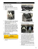
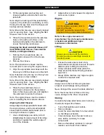
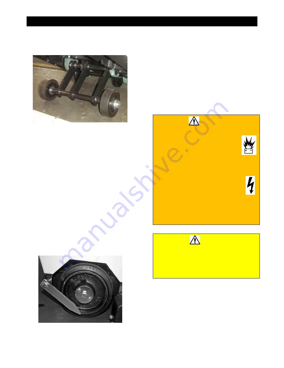
Replacing the Front Wheels
Replace the front wheels when damaged
and/or affecting saw performance.
Front Wheels
1. Move the saw to level ground. Use a jack
to lift the front wheels off the ground.
2. Remove the setscrew from the set collar
and remove the set collar.
3. Remove the wheel and flat washers from
the front axle.
4. Place a flat washer and then a new wheel
onto the front axle.
5. Place a flat washer and then the set collar
up against the wheel on the front axle.
6. Retighten the setscrew into the set collar to
secure.
7. Repeat steps 2 through 6 for the second
front wheel.
8. Remove the jack stand(s) and slowly lower
the saw until the wheels are firmly touching
the ground.
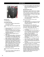
Replacing the Rear Wheels
Replace the rear wheels when damaged
and/or affecting saw performance.
Rear Wheel
1. Move the saw to level ground. Use a jack
to lift the rear wheels off the ground.
2. Remove the three screws from the wheel.
3. Remove the wheel mount washer and
wheel from the rear axle.
4. Place a new wheel onto the rear axle.
5. Replace the wheel mount washer and
retighten the three screws to secure the
wheel.
6. Repeat steps 2 through 5 for the second
rear wheel.
7. Remove the jack stand(s) and slowly lower
the saw until the wheels are firmly touching
the ground.
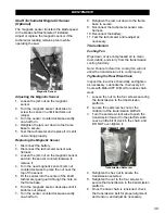
Battery
WARNING
•
Ignitable explosive gases are emitted
from the battery. DO NOT
expose the battery to sparks or
open flames, and keep the area
around the battery well-
ventilated.
•
Disconnect the battery prior to servicing
the saw (unless stated otherwise).
•
Always keep the battery cable
clamps away from the battery
terminals when the battery is
disconnected to avoid accidental
connections while servicing.
•
Always be sure to connect the battery
cables to the proper terminal when
reconnecting.
CAUTION
•
Use a proper battery tester when testing
the battery strength.
•
Use protective eyewear or a face shield
and avoid contact with the skin when
handling/servicing the battery.
The saw contains a charged battery with one
positive cable lead and one negative cable
lead. To power the hydraulic lift pump. The
battery can be accessed by removing the rear
cover screen.
37
Summary of Contents for CC3538JK Series
Page 1: ...CORE CUT OPERATOR S MANUAL CC3538JK Electronic Fuel Injection May 2020 Rev 20 00 Part 1802723...
Page 2: ......
Page 47: ...REFERENCES 47...
Page 48: ...REFERENCES 48...
Page 49: ...REFERENCES 49...
Page 51: ...REFERENCES...

