MAINTENANCE
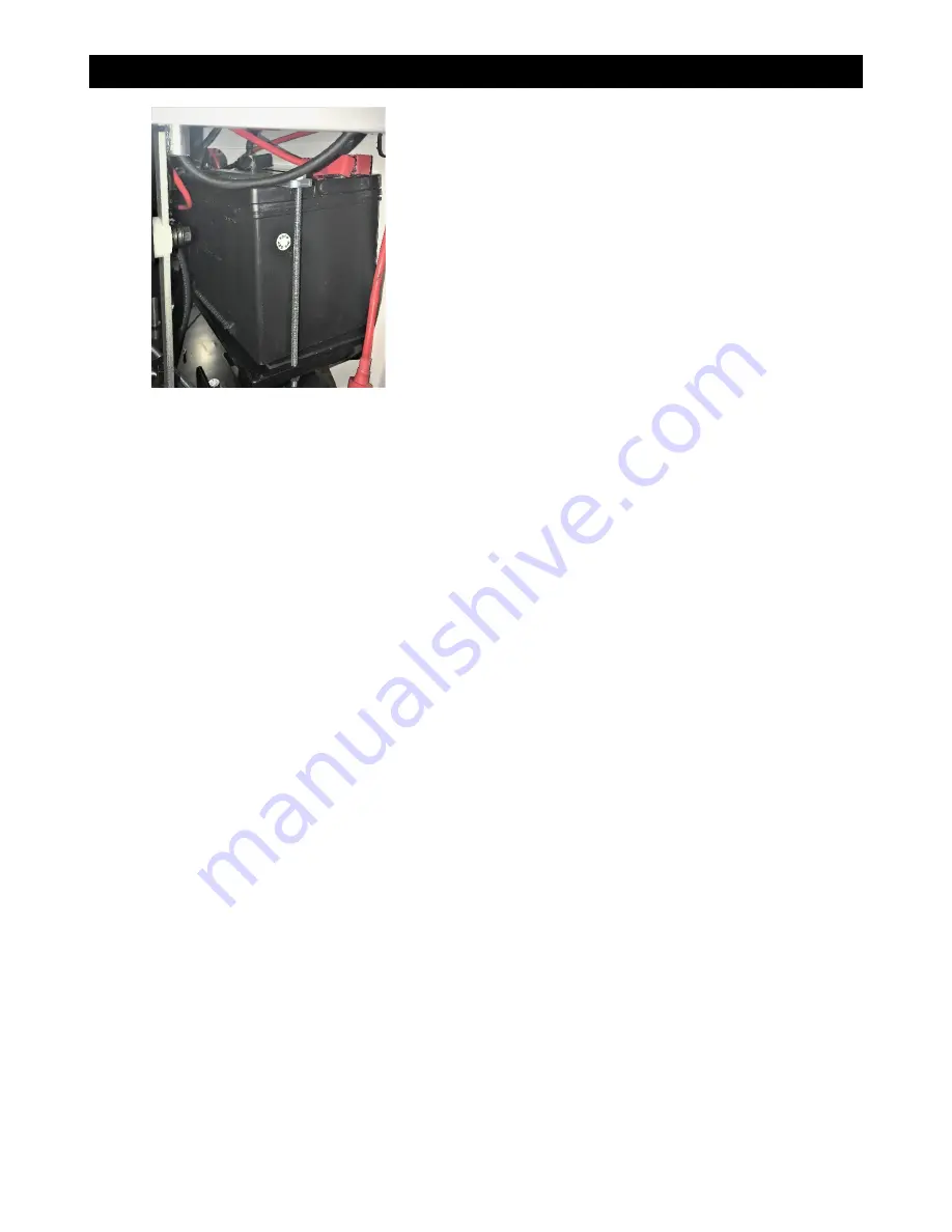
Battery
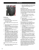
Battery Type
12 Volt, Group 34
Servicing the Battery
1. Disconnect the negative cable lead from
the negative terminal.
NOTE: Always disconnect the negative cable
first
.
2. Disconnect the positive cable lead from the
positive terminal.
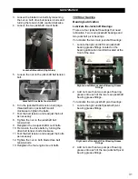
3. Unsecure the battery from the hold-down
bracket by removing the two lock nuts from
the battery hold-down tie rods and lift the
hold-down bracket off.
4. Carefully remove the battery from the
battery tray.
5. When replacing the battery, carefully place
a new battery into the battery tray. Bring
the old battery to a recycling facility; many
battery retailers also accept old batteries.
6. When cleaning the battery, inspect the
terminals, clamps, and cables for damages
and corrosion. Clean the terminals and
clamps using a wire brush, or use another
approved technique for cleaning. Use acid-
free, acid-resistant grease to grease the
battery clamps and terminals. Carefully
place the battery back into the battery.
7. Reconnect the positive cable lead to the
positive battery terminal.
NOTE: Always reconnect the positive cable
first
.
8. Reconnect the negative cable lead to the
negative battery terminal.
9. Re-secure the battery to the hold down top
brace by reinstalling the lock nuts onto the
two tie rod bolts and tighten them to
secure.
Speed Control Lever
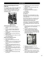
Adjusting the Speed Control Lever Linkage
Adjust the speed control lever linkage when it
is set incorrectly; for example, when the saw is
in neutral, but the lever is closer to the forward
or reverse position.
1. Start the engine and move the speed
control lever forward or backward to find
the neutral position.
Note: The saw should not move at all
.
2. Stop the engine.
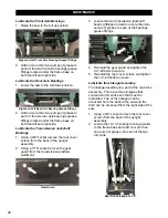
3. Disconnect the 10-1/2” linkage from the bell
crank. (See “Rear Drive Assembly” in the
CC3500J Parts List)
Note: DO NOT move the 7-3/4” when
disconnecting the 10-1/2” linkage to keep the
saw in the neutral position. (See “Rear Drive
Assembly” in the CC3500J Parts List)
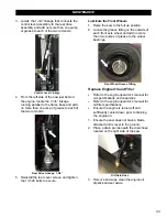
4. Loosen the threaded rod nuts on the 10-
1/2” linkage.
5. Turn the threaded rod to either lengthen or
shorten the linkage, which will move the
speed control lever toward the neutral
position on the control panel.
6. When the speed control lever is in the
neutral position on the control panel,
retighten the threaded rod nuts on the 10-
1/2” linkage.
7. Reconnect the 10-1/2” linkage to the bell
crank. DO NOT move the 7-3/4” linkage.
8. Remove all tools from the area. Start the
engine to check the speed control lever for
accuracy.
9. If the speed control lever is still not properly
aligned, repeat step 1–8 to readjust.
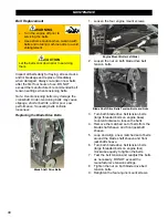
Adjusting the Speed Control Lever Friction
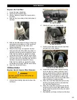
Adjust the screw and nut on the speed control
lever (through friction spacer) to change the
amount of friction felt when moving the lever
forward or backward. Loosen the bolt a small
amount to make it easier to move the lever, or
tighten the bolt a small amount to make it
harder to move the lever.
38
Summary of Contents for CC3538JK Series
Page 1: ...CORE CUT OPERATOR S MANUAL CC3538JK Electronic Fuel Injection May 2020 Rev 20 00 Part 1802723...
Page 2: ......
Page 47: ...REFERENCES 47...
Page 48: ...REFERENCES 48...
Page 49: ...REFERENCES 49...
Page 51: ...REFERENCES...


