OPERATING
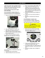
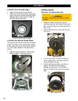
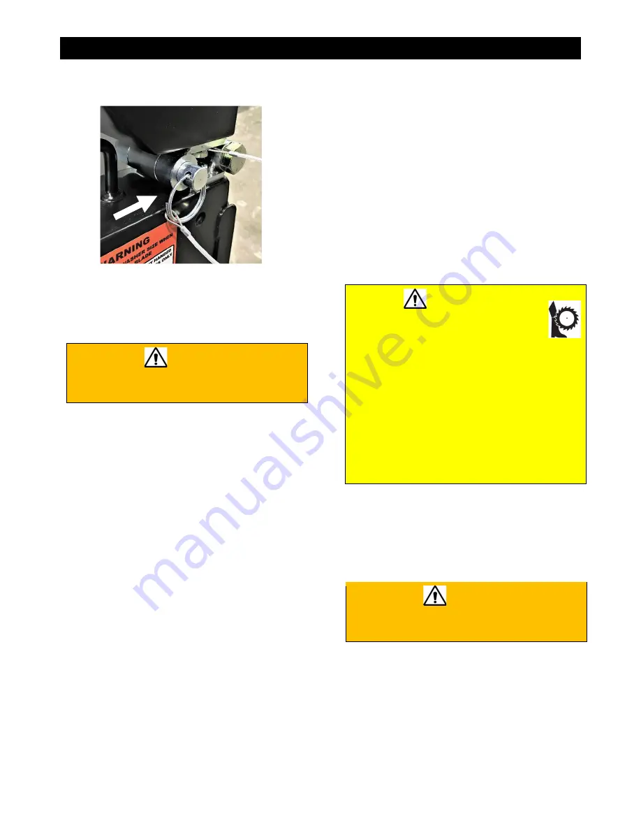
prior to pivoting the front of the blade guard
180° (fully upward).
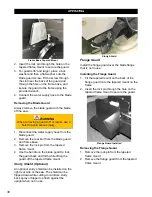
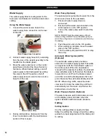
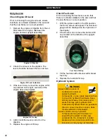
Detent Pin (26” Blade Guards and Larger)
3. On the pivoted guards, insert the detent pin
through the interlocking barrels on the top
of the guard to secure the front of the guard
as shown above.
WARNING
Failure to fully pivot and secure the front of
the guard may cause serious injuries.
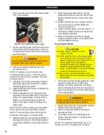
4. Remove the blade shaft bolt using the
provided wrench.
NOTE: Clockwise loosens on right side,
counterclockwise loosens on left side (when
viewed from the operating position) using the
provided wrench.
5. Carefully remove the outer flange. Inspect
the flange assembly and clean or replace
dirty/damaged components.
6. Align and fit the outer flange and flange pin
through the blade.
7. Place the blade and outer flange into the
alignment hole and blade arbor of the inner
flange. For large blades, carefully roll the
blade up to the inner flange. Adjust the
height of the saw to align the flange and
blade arbor.
NOTE: Point the arrow stamped on the blade
in the direction of the blade shaft’s rotation
.
NOTE: The outer flange should fit snug with
the blade, inner flange, and blade shaft
.
8. Slightly rotate the outer flange and blade in
the opposite direction of the blade rotation
to eliminate backlash (looseness) between
parts.
9. Place the wedge lock washer onto the
blade shaft bolt and insert the bolt into the
blade shaft through the center of the outer
flange.
10. Tighten the bolt by hand. Slowly lower the
saw, if necessary, until the blade just
touches the ground.
11. Tighten the bolt again, using the wrench, to
125 ft-lb (170 Nm) minimum to secure the
outer flange and blade.
12. Remove the detent pin from the guard
hinge and pivot the front of the guard down
over the blade to secure.
Removing the Blade
CAUTION
DO NOT remove a blade with the
engine running.
DO NOT pivot the front of the blade guard
up or down when removing very large
blades. Attempting to pivot the front of a
heavy guard when the guard is
positioned higher up for blade removal
makes the guard difficult to lift and/or
lower. In this situation, remove the blade
guard front instead of pivoting it.
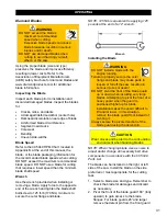
Always secure the pivoted section of the
blade guard using the detent pin (guards
26” and up).
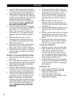
1. Pivot the front of the blade guard 180° (fully
upward) to gain access to the blade
flanges. For blade guards 26” and larger
remove the detent pin from the front guard
prior to pivoting the front of the blade guard
180° (fully upward).
WARNING
Failure to fully pivot and secure the front of
the guard may cause serious injuries.
2. Slowly lower the saw, if necessary, until the
blade just touches the ground.
3. Remove the blade shaft bolt using the
provided wrench.
4. Carefully remove the outer flange and
blade. Place the blade in an appropriate
storage location.
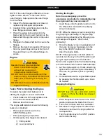
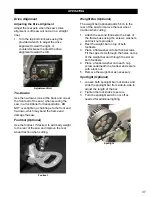
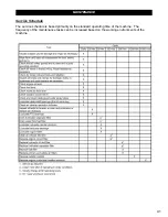
NOTE: An onboard blade storage arbor, for
blades up to 36”, is available as an option.
32
Summary of Contents for CC5049D
Page 1: ...CORE CUT OPERATOR S MANUAL CC5049D Rev 21 00 Part 1802721...
Page 2: ......
Page 8: ...INTRODUCTION CC5049D Controls 8...
Page 11: ...INTRODUCTION CC5049D Specifications 11...
Page 58: ...REFERENCES 58...
Page 59: ...REFERENCES 59...
Page 60: ...REFERENCES 60...
Page 67: ......


