MAINTENANCE
2. Screw the spring plungers slightly out to let
the speed control lever move easily into
and out of the
STOP/PARK
position. Screw
the spring plungers in slightly, to let the
speed control lever move firmly into and
out of the
STOP/PARK
position.
3. Retighten both hex nuts to secure.
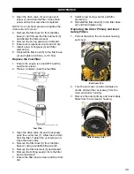
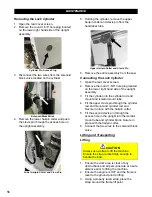
Inner Blade Flange
Inner Flange
Installing the Inner Blade Flange
1. Inspect the inner flange for damages.
Clean or replace damaged components as
necessary.
2. Align the flange with the blade shaft key
and place the flange onto the blade shaft.
3. Apply Loctite 262 (red) or an equivalent to
the setscrew threads.
4. Tighten the setscrew(s) into the back of the
inner flange to secure.
Removing the Inner Blade Flange
1. Remove the setscrew(s) from the back of
the inner flange using an Allen wrench.
2. Carefully remove the flange from the blade
shaft.
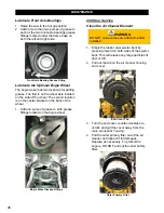
Maximum Cutting Depth Stop Bolts
Always adjust the maximum cutting depth stop
bolts when changing to a larger flange size to
avoid damaging the blade flanges.
1. Raise the saw to gain access to the
maximum cutting depth stop bolts
underneath the frame base.
WARNING
Raise the saw to a proper height for
access when working underneath the
saw. Use chocks to block the wheels,
and fit blocks or jacks under the frame edges
at the front and back of the frame
.
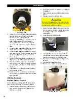
2. Loosen the jam nut on both bolts.
3. Turn the bolts counterclockwise to
decrease the maximum cutting depth, or
turn the bolts clockwise to increase the
maximum cutting depth.
NOTE: Both bolts must be the same length
when finished
.
Maximum Depth Stop Bolt
4. Bottom out the jam nut on each bolt with
the frame base to secure the bolts.
5. Remove all tools from the area and lower
the saw completely. The blade flanges
must be at least 1/4” from the ground to
prevent component damage.
6. Readjust the depth stop bolts as
necessary.
NOTE: Make sure both skid plates on the front
of the saw are in the correct set of holes in
order to lower the saw completely (refer to
Appendix B).
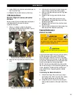
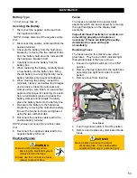
Handlebar Lock Cylinder (Optional)
The handlebar lock cylinder must be serviced
by Diamond Products if the handlebars can be
moved up or down in excess amounts when
locked in place (movement may feel sluggish).
Send the entire assembly to Diamond Products
to be recharged or pressurized.
55
Summary of Contents for CC5049D
Page 1: ...CORE CUT OPERATOR S MANUAL CC5049D Rev 21 00 Part 1802721...
Page 2: ......
Page 8: ...INTRODUCTION CC5049D Controls 8...
Page 11: ...INTRODUCTION CC5049D Specifications 11...
Page 58: ...REFERENCES 58...
Page 59: ...REFERENCES 59...
Page 60: ...REFERENCES 60...
Page 67: ......

