MAINTENANCE
Removing the Lock Cylinder
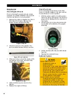
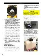
1. Open the rear cover screen.
2. Remove the round 1-5/8” hole plug located
on the lower right hand side of the upright
assembly.
Cylinder Pin Access Plug
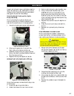
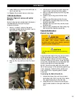
3. Disconnect the two wires from the solenoid
block valve located on the cylinder.
Solenoid Block Wires
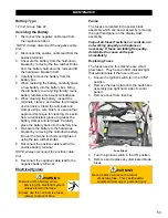
4. Remove the lower hairpin cotter and push
the clevis pin through the access hole on
the upright assembly.
Lower Hairpin Cotter and Clevis Pin
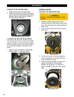
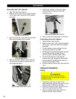
5. Holding the cylinder, remove the upper
hairpin cotter and clevis pin from the
handlebar tube.
Upper Hairpin Cotter and Clevis Pin
6. Remove the entire assembly from the saw.
Connecting the Lock Cylinder
1. Open the rear cover screen.
2. Remove the round 1-5/8” hole plug located
on the lower right hand side of the upright
assembly.
3. Fit the cylinder into the cylinder rod end
mount and isolator mount tube.
4. Fit the upper clevis pin through the cylinder
rod end mount and cylinder rod end.
Secure in place with the hairpin cotter.
5. Fit the second clevis pin through the
access hole in the upright into the isolator
mount tube and cylinder block. Secure in
place with the hairpin cotter.
6. Connect the two wires to the solenoid block
valve.
Lifting and Transporting
Lifting
CAUTION
Always use a strap to lift the machine.
Ensure the strap is rated high enough to
handle the load.
1. Ensure the work area is clear of any
obstructions and all personnel are at a safe
distance prior to lifting the machine.
2. Ensure the engine is
OFF
and the frame is
level to the ground prior to lifting.
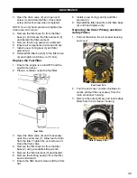
3. Using a properly rated strap, place the
strap around the frame lift point.
56
Summary of Contents for CC5049D
Page 1: ...CORE CUT OPERATOR S MANUAL CC5049D Rev 21 00 Part 1802721...
Page 2: ......
Page 8: ...INTRODUCTION CC5049D Controls 8...
Page 11: ...INTRODUCTION CC5049D Specifications 11...
Page 58: ...REFERENCES 58...
Page 59: ...REFERENCES 59...
Page 60: ...REFERENCES 60...
Page 67: ......

