background image


CC7574DKV OPERATOR’S MANUAL

Concrete Cutting 

WARNING 

  DO NOT expose yourself or anyone else 

to the direct line of the blade while 
operating the saw. 

  The direct work area should not contain 

buried or embedded electrical, gas, or 
water lines that could be damaged 
and/or cause personal injury or death. 

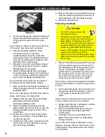
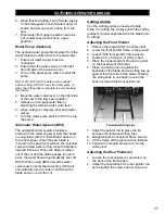
Note: Always raise the blade to provide proper 
clearance between the blade and the ground 
when maneuvering the saw. 

Helpful Hints Prior to Cutting 

Keep the following in mind for better efficiency 
while cutting: 

  Use just enough handle pressure to guide 

the saw down the cutting line. DO NOT 
forcibly direct (twist) the saw from side to 
side when cutting. DO NOT jam, cock, or 
wedge the blade in a cut. 

  Moving too quickly when cutting may stall 

the saw, or may cause the blade to climb 
out from the cut. If the saw stalls while 
cutting, put the saw in neutral and raise the 
blade from the cut to restart the engine. 

  Avoid sawing excessively deep to preserve 

the blade and reduce sawing costs. 

  DO NOT lower the blade too quickly or 

move the saw forward too quickly when 
finishing a partial-cut to avoid forcing the 
blade into the concrete. 

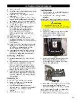
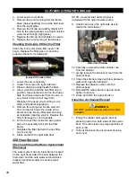
  Always have a proper water flow when 

cutting for maximum blade efficiency. Using 
too much water when cutting will make the 
slurry look clear. Not using enough water 
will make the slurry look thick and pasty. 

  Refer to the Diamond Products’ Guide for 

Professional Concrete Cutters for 
additional cutting tips and information. 

Tasks Prior to Cutting 

Complete the following tasks prior to cutting: 

  Align the cutting guide(s) with the blade. 

  Clearly mark the cutting line. 

  Turn off all electricity, gas, and water 

around the direct work area. 
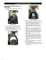
Making a Cut 

1.  Align the blade and cutting guide(s) with 

the cut line. 

2.  Start the engine and allow to idle briefly 

before going to full power. 

3.  If the saw is equipped with a clutch 

(optional), turn on the 

Blade Clutch

 switch 

with engine at idle to start the blade 
rotation. 

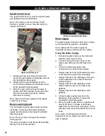
4.  Turn on the water. 
5.  Move the lever on the right side water valve 

to the fully open position. 

6.  Adjust the water flow using the left side 

water valve. 

7. 

Lower the blade to just above the cutting 
surface and zero the blade by pressing the 
“Zero Blade” button on the display panel.


8. 

 Slowly lower the blade into the surface to 
no more than 2” deep. Make the initial pass 
across the entire cutting line using the most 
effective travel speed. If the blade is 
coming up out of the cut, decrease travel 
speed and/or feed depth.  

DO NOT CUT 

FULL DEPTH IN ONE PASS

.


9. 

If you are cutting more than 2” deep, you 
can finish the job in less time and effort by 
step cutting. Cut a 2” depth on the initial 
pass, followed by deeper passes. On 
repeated passes, the blade will tend to 
follow the previous cut.


10. Raise the blade out of the cut and 

reposition the saw at the start of the cut 
line. DO NOT move backwards with the 
blade in a previous cut. 

11. At the start of the cut line, lower the blade 

back into the cut and make a second, 
deeper pass across the entire cutting line. 

12. Continue the step-cut process to reach the 

maximum depth. DO NOT cut any deeper 
than required. 

Making a Cut Using the Blade Depth 
Stop 

1.  Align the blade and cutting guide(s) with 

the cut line. 

2.  Start the engine and allow to idle briefly 

before going to full power. 

3.  If the saw is equipped with a clutch 

(optional), turn on the 

Blade Clutch

 switch 

with engine at idle to start the blade 
rotation. 

38

Summary of Contents for CC7574DKV

Page 1: ...CORE CUT OPERATOR S MANUAL CC7574DKV CC7574DKV 3 MAY 2022 Part 1802742 01...

Page 2: ......

Page 3: ...orting Safety 17 Lifting Safety 17 Display Panel Controller 18 Controller Features 18 Flat Screen Display 18 Function Keys 21 Soft Key Commands 21 Main Menu Key 22 Engine Diagnostics 23 User Settings...

Page 4: ...Using the Blade Depth Stop 38 Continuing a Partial Cut 39 Finishing a Cut 39 Hood Operation 39 Shifting the Three Speed Transmission 39 Maintenance 40 General 40 Maintenance Tools 40 Pre Maintenance P...

Page 5: ...the Fuel Filter 51 Replacing the Outer Primary and Inner Safety Filters 52 1000 Hour Service 53 Changing the Radiator Fluid and Hoses 53 Lubricate the Blade Shaft Seals 53 1500 Service Hours 53 Replac...

Page 6: ...arked Regeneration 61 Requesting a Parked Regeneration 61 References 63 Appendix A 63 Troubleshooting 63 Appendix B 65 CC7574DKV RPM Chart 65 CC7574DKV 3 RPM Charts 65 CC7574DKV Blade Size Conversion...

Page 7: ...rious injuries and or death All operators must be properly trained or supervised by experienced personnel prior to using this equipment and should understand the risks and hazards involved Diamond Pro...

Page 8: ...erator to move saw forward backward with ignition switch at ON 8 LED Spotlight Switch Activates spotlight 9 LED Light Bar Switch Optional Activates the light bar 10 Water Pump Switch Optional Activate...

Page 9: ...ls water flow rate Connects to the water source hose 22 Water On Off Control Valve Turns water flow to the saw blade on and off 23 Fuel Filler Cap Fill Port 24 LED Spot Light Illuminates the work area...

Page 10: ...1651 C Saw Length Maximum 143 3632 D Handle Extension Maximum 28 711 E Frame Length 53 3 4 1365 F Wheel Base Length 24 1 4 616 G Saw Width 36 1 2 927 H Frame Width 29 737 I Front Wheels Inside Width 2...

Page 11: ...CC7574DKV OPERATOR S MANUAL CC7574DKV Specifications 11...

Page 12: ...CC7574DKV OPERATOR S MANUAL CC7574DKV 3 Specifications 12...

Page 13: ...not followed WARNING Serious injuries and or death could occur if these instructions are not followed CAUTION Mild and or moderate injuries could occur if these instructions are not followed Propositi...

Page 14: ...ll guards and access panels unless stated otherwise prior to operating the equipment Always pivot front of blade guard fully closed to avoid serious injuries DO NOT Assume the equipment will remain st...

Page 15: ...nents immediately DO NOT expose yourself or anyone else to the direct line of the blade when operating the equipment Always use an appropriate size blade and the correct blade type based on the cuttin...

Page 16: ...ow to turn off the engine quickly for emergency purposes Make sure the equipment is in neutral when starting the engine Fill the fuel tank and check the oil level prior to starting the engine Keep all...

Page 17: ...the gearbox bearings Under tensioning belts may cause slippage shorter belt life and or poor equipment performance Squealing belts indicate looseness DO NOT use old and new belts together on the same...

Page 18: ...bout the configuration Controller Features Flat Screen Display The flat screen displays the gauges dashboard warning icons soft key commands fault messages and menu options for setup and configuration...

Page 19: ...Level Red icon will illuminate when a low fuel level condition exists Water in Fuel Red icon will illuminate if water is detected in the fuel tank Battery Voltage Red icon will illuminate when a low b...

Page 20: ...erature Lamp Red icon displays during active DPF regeneration when the DPF outlet temperature is greater than 450 C 842 F and post engine fuel injection is occurring Regeneration Needed Yellow icon wi...

Page 21: ...irectly below it The soft key options associated with this saw are listed below Soft Key Description Blade Size Toggles to the blade size selection screen Parameter Screen Selection Toggles between Bl...

Page 22: ...cursor down Plus Increases a numerical selection Minus Decreases a numerical selection Return Returns to previous screen Reset Resets the service reminder hours on maintenance milestones when the main...

Page 23: ...s 2 Stored Faults Recall Active Faults This screen displays active faults or warnings from the Electronic Control Unit ECU Each diagnostic is shown with the appropriate Suspect Parameter Number SPN Fa...

Page 24: ...Indicator FMI Text Description if available and the source of the device that transmitted the diagnostic message User Settings The user setting is a series of two screens that display the following it...

Page 25: ...rator to choose between standard US and metric units Set Clock This option allows the operator to set and update save setting the time on the clock display The clock will remain operational when the u...

Page 26: ...the option There is also an option to request a regeneration from this menu See the Maintenance section of this manual for additional information regarding the DPF regeneration process Service Reminde...

Page 27: ...ngine Model 3 Engine Serial Number 4 Rated Power 5 Rated Speed 6 Software Revision Lamp Information The lamp information screen is informational only There are a series of four screens that can be tog...

Page 28: ...Refer to the RPM and Blade Size Conversion Charts located in Appendix B at the end of this manual To select the proper blade size 1 Scroll through the available blade sizes using the function keys as...

Page 29: ...or millimeters to show the depth of the cut Set the Blade Depth Stop Ensure that the saw is operating and all safety precautions are being followed 1 Follow the Zero the Blade procedure listed above 2...

Page 30: ...f the weight bar and through the slot on both footrests 4 Install a fender washer onto each screw underneath the footrest and secure with a lock nut 5 Remove the weight bar as necessary Spotlight 1 Lo...

Page 31: ...l down 3 Remove the fuel tank cap 4 Fill the fuel tank with ultra low sulfur diesel fuel DO NOT overfill the tank for expansion purposes Refer to the engine manual for information on appropriate diese...

Page 32: ...uard 3 Remove the lock pin from the tapered frame mount 4 Use the handle on the blade guard to rock the guard back and forth while lifting the guard off the tapered frame mount Flange Guard Install th...

Page 33: ...nd be alert to the surrounding environment when handling blades WARNING DO NOT install a blade with the engine running Failure to secure the outer flange and blade may cause parts to loosen or fall of...

Page 34: ...Remove the detent pin guards 26 and up from the guard hinge and pivot the front of the guard down over the blade to secure 13 Re insert the detent pin Removing the Blade CAUTION DO NOT remove a blade...

Page 35: ...red 1 E Stop active 2 Low coolant level 3 Radiator door open Starting the Engine Notice In an emergency press the emergency stop button to immediately stop the engine and any saw movement 1 Insert the...

Page 36: ...nt of the operator Blade Lowering Speed Valve Water Supply The water supply minimizes dust when cutting and cools the fuel gearbox and blade Note Always test the water supply for adequate pressure and...

Page 37: ...water to flow when the blade is lowered into a cut When the blade is raised out of the cut and the blade passes the zero point the water flow will automatically shut off NOTE When using AWS adjust the...

Page 38: ...e Turn off all electricity gas and water around the direct work area Making a Cut 1 Align the blade and cutting guide s with the cut line 2 Start the engine and allow to idle briefly before going to f...

Page 39: ...ncrete Use extreme caution to make sure the blade is perfectly aligned within the cut DO NOT continue cutting until the blade is aligned within the cut 3 Continue the step cut process using the blade...

Page 40: ...emove the cutting blade prior to starting any maintenance Place the saw on a level surface with the engine turned off and the emergency stop activated Ensure there is adequate lighting in the work are...

Page 41: ...not spray water into the exhaust pipe or air filter Part Lubrication WARNING DO NOT grease parts with the engine running Lubricate all necessary parts on schedule for maximum saw efficiency Occasional...

Page 42: ...S MANUAL Service Schedule The service schedule is based primarily on the standard operating time of the machine The frequency of the maintenance tasks can be increased based on the working environment...

Page 43: ...evel position 1 If fuel level is low as indicated by the low fuel level icon on the display panel remove the fuel tank fill cap located on the left top side of the upright assembly Fuel Tank Fill Cap...

Page 44: ...ivalent to just below where the fill port extends into the hydraulic pump Do not overfill as this will cause oil leakage through the breather cap when raising the saw 5 Replace the breather cap and re...

Page 45: ...the restriction indicator reset button on the top of the indicator to reset the unit after the air filters has been serviced Rubber Dust Ejector Boot The rubber dust ejector boot valve ejects debris a...

Page 46: ...ccess it unlatch and open the right side door The fitting is located at the frame base just in front of the cooling fan Pivot Pin Grease Fitting Lubricate Front Axle Pivot Bearings 1 Raise the saw to...

Page 47: ...r cap and retighten to secure Changing the Upper Gearbox Oil 3 Speed Change the upper gearbox oil every 100 hours 3 Speed Gearbox 1 Lower the saw to level the frame 2 Place a drain pan under the gearb...

Page 48: ...ged or not cleanable 6 Fit the bronze filter inside the spring and place the assembly back into the filter barrel 7 Retighten the filter barrel to the hex filter cap to secure 8 Close and latch the ri...

Page 49: ...r into the air cleaner housing over the inner safety filter and gently push the filter into the unit until it feels secure 8 Place the end cover tightly up against the ridge at the end of the air clea...

Page 50: ...ance with city state and federal regulations 11 Shut oil drain valve and replace red plastic drain plug 12 Install a new filter on the engine Lubricate the rubber gasket on the filter with a film of o...

Page 51: ...move the electrical connector from the drainage cap and remove the cap 6 Remove the fuel water separator filter using a filter wrench 7 Dispose of the filter according to city state and federal regula...

Page 52: ...r housing DO NOT allow dust to enter the air intake tube when cleaning or replacing parts 5 Place the new inner safety filter into the air cleaner housing until it is fully seated 6 Place the new oute...

Page 53: ...hoses and secure them using the hose clamps 9 Close the rear cover screen and latch to secure 10 Add a 50 50 mix of water and antifreeze as called out in the CC7574DKV Parts List to the expansion tan...

Page 54: ...grease cap to the pivot housing 8 Close the rear cover screen and latch to secure Adjusting the Spring Plungers Adjust the spring plungers if the speed control lever feels too tight or too loose when...

Page 55: ...clockwise to adjust the drive alignment toward the left Adjustment Bolt Wheels WARNING Raise the saw to a proper height for access when working underneath the saw Use chocks to block the wheels and fi...

Page 56: ...flange size and belt size to avoid damaging saw components Refer to the CC7574DKV Parts List for additional information 1 Raise the saw to gain access to the maximum cutting depth bolts underneath th...

Page 57: ...wo wires to the solenoid block valve according to the wiring diagrams in the CC7574DKV Parts List Battery WARNING Ignitable explosive gases are emitted from the battery DO NOT expose the battery to sp...

Page 58: ...ive cable lead to the negative battery terminal 10 Reinsert the hold down batter lid over the two tie rod bolts and tighten it using the two ratchet knobs 11 Close and latch the left side door Electri...

Page 59: ...essary DO NOT exceed the manufacturer s tension settings 7 Tighten the nut on both blade drive belt tension bolts down to the engine foot 8 Retighten the two engine cradle screws 9 Close and latch the...

Page 60: ...ring the saw for longer time frames Drain the water lines hoses Turn off all switches and controls Lower the saw completely to remove strain on the lifting mechanism Clean and wipe down the saw to rem...

Page 61: ...e into contact with combustible materials During active regeneration the display panel will show the active regen red status icon on the display panel Red Active Regen in Process Icon Parked Regenerat...

Page 62: ...eration is occurring This will abort the regeneration process and require to start the process over CAUTION Once the process has started it can be stopped by selecting the Stop Regen soft key DO NOT s...

Page 63: ...the problem is not cleared a shutdown warning will be displayed the next time the keyed is turned to the on position Coolant level is extremely low Fill the coolant system in accordance with the Addin...

Page 64: ...NOT twist blade from side to side Wrong blade Contact dealer manufacturer of blade 9 Short belt life Loose belts causing slippage Check and adjust belt tension Sheaves misaligned Use straightedge to c...

Page 65: ...CC7574DKV OPERATOR S MANUAL Appendix B CC7574DKV RPM Chart CC7574DKV 3 RPM Charts 65...

Page 66: ...CC7574DKV OPERATOR S MANUAL 66...

Page 67: ...CC7574DKV OPERATOR S MANUAL CC7574DKV Blade Size Conversion Chart 67...

Page 68: ...CC7574DKV OPERATOR S MANUAL CC7574DKV 3 Blade Size Conversion Chart 68...

Page 69: ...and Drilling Association www csda org The CSDA has many helpful concrete cutting publications available to members and non members 4 Association of Equipment Manufacturers www aem org The AEM has a va...

Page 70: ...Serial Numbers Record the saw s serial number below for future reference and customer service purposes Record the engine s model and serial numbers below for future reference and customer service purp...

Page 71: ......

Page 72: ...ts Elyria Ohio factory or at a point designated by it of such parts as shall appear to us upon inspection at such parts to have been defective in material or workmanship with expense for transportatio...

Reviews: