

CC7574DKV OPERATOR’S MANUAL
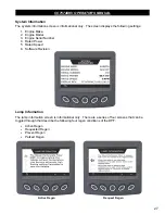
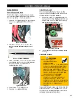
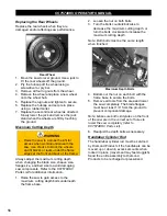
Control Panel
Do not spay water on the control panel to
clean. Use a damp cloth or compressed air to
clean electrical components. Dry the control
panel after cleaning.
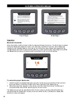
Display Screen and Camera Lens
Do not spray water on the display screen to
clean. Use a damp cloth to wipe it clean and
dry the screen with a lint free cloth.
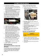
Engine
Use a mild detergent and water to clean the
engine. Do not to spray water forcefully on the
engine to prevent damage to components.
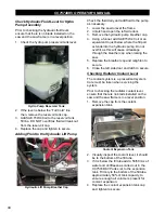
NOTE: Do not spray water into the exhaust
pipe or air filter.
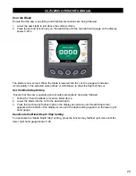
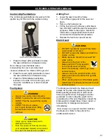
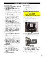
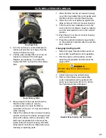
Part Lubrication
WARNING
DO NOT grease parts with the
engine running.
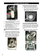
Lubricate all necessary parts on schedule for
maximum saw efficiency. Occasionally
lubricate controls, cables, hinges, latches, and
linkages with a spray lubricant when
movement becomes stiff and/or sluggish. Use
one to two full pumps of NLGI No. 2 premium,
lithium-based grease when lubricating all
grease fittings.
NOTE: Use more grease on bearing grease
fittings if they are too hot to touch after
completing work.
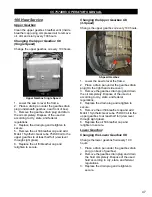
Post Cleaning
•
Lubricate the machine as required.
•
Dry all electrical components using
compressed air.
•
Do not start the machine until it has had
time to thoroughly dry.
.
41
Summary of Contents for CC7574DKV
Page 1: ...CORE CUT OPERATOR S MANUAL CC7574DKV CC7574DKV 3 MAY 2022 Part 1802742 01...
Page 2: ......
Page 11: ...CC7574DKV OPERATOR S MANUAL CC7574DKV Specifications 11...
Page 12: ...CC7574DKV OPERATOR S MANUAL CC7574DKV 3 Specifications 12...
Page 65: ...CC7574DKV OPERATOR S MANUAL Appendix B CC7574DKV RPM Chart CC7574DKV 3 RPM Charts 65...
Page 66: ...CC7574DKV OPERATOR S MANUAL 66...
Page 67: ...CC7574DKV OPERATOR S MANUAL CC7574DKV Blade Size Conversion Chart 67...
Page 68: ...CC7574DKV OPERATOR S MANUAL CC7574DKV 3 Blade Size Conversion Chart 68...
Page 71: ......