background image

MACHINE SET UP &INSTALLATION 

UNCRATING MACHINE

Be sure and check packing carton for any damage. 
Immediately report any damage to carrier. Check 
contents of package to ensure that the following 
items are included:  Machine, batteries (x2), 
squeegee assembly, battery charger, and pad driver. 

BATTERY CONNECTIONS

The batteries are already in the machine upon 
delivery; however, you will need to connect the 
cables to the battery posts.  

 :  Batteries emit hydrogen gas.  

Explosion or fire can result from hydrogen gas. 
Keep sparks and open flames away! Keep battery 
compartment open when charging. 
1. Be sure power switch is in the “off” position.
2. Open recovery tank to gain access to battery

compartment.

3. Carefully place the two batteries into the

compartment as shown in figure below. Place
the battery brace at the rear of the two batteries.

DO NOT DROP BATTERIES INTO 
COMPARTMENT!

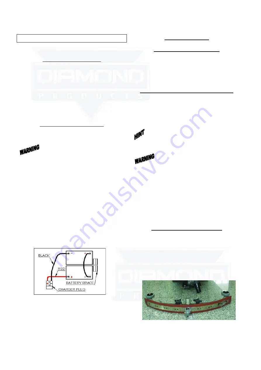
4. Connect battery cables to posts in numbered

order as shown in drawing below. (RED to
POSITIVE and BLACK to NEGATIVE)

5. Apply a coat or protective spray on the cable

connections to prevent battery corrosion.

MACHINE SET UP

PRE-OPERATION CHECKS

1. Sweep or dust mop the surface to be cleaned.
2. Check battery meter to make sure batteries are

fully charged. (see BATTERY CHARGING)

3. Check that squeegee is properly installed.
4. Check that brush / pad is properly installed.

INSTALLING PAD DRIVER OR BRUSH

1. Ensure that the machine is turned off
2. Lower brush head assembly to the floor by

stepping on the foot pedal and pushing pedal
forward.

3. Tilt the machine backward to access the drive

motor hub.

: Remove the squeegee assembly prior to 

tilting the machine backwards.  It makes the 
process faster and easier. 

: Do not keep the machine tilted back for 

a long time.  This could cause battery acid to leak 
from the batteries. 
4. If using a pad driver, first attach the

appropriate pad to the pad driver surface.

5. Mount the pad driver or brush to the drive

motor hub by lining up the three studs with the
three holes in the drive motor hub.  Once in the
holes, rotate the driver toward the spring clip
to lock driver into place.

MOUNTING THE SQUEEGEE

1. Pull back on the squeegee lift lever to raise the

squeegee bracket up.

2. Loosen the two knobs on the squeegee and

slide the squeegee into the slots at the rear of
the squeegee bracket. (the wheels on the
squeegee point to the back)

3. Tighten the knobs securely.
.

-5-

Operator's Manual

                                                      Diamond Products

Summary of Contents for CROWN G20

Page 1: ...ANT READ OPERATOR S MANUAL CAREFULLY Please fill out return your warranty card OPERATOR S MANUAL CROWN G20 GS20 AUTO SCRUBBERS DP80020 DP80120 Diamond Products www diamondproductsus com Printed in the...

Page 2: ...ng or servicing this unit should be directed to your nearest dealer Information in this document is subject to change without notice and does not represent a commitment on the part of Diamond Products...

Page 3: ...RE LEAVING OR SERVICING MACHINE Stop machine on level ground Turn machine off 5 WHEN SERVICING MACHINE Read operators manual thoroughly prior to operating or servicing this machine Use manufacturer su...

Page 4: ...t levers 11 Rear solution fill 12 Circuit breakers 13 Squeegee lift lever 14 Control housing 15 Solution tank 16 Transport wheels 17 Scrub head 18 Scrub head skirt 19 Protective rollers 20 Front solut...

Page 5: ...ON CHECKS 1 Sweep or dust mop the surface to be cleaned 2 Check battery meter to make sure batteries are fully charged see BATTERY CHARGING 3 Check that squeegee is properly installed 4 Check that bru...

Page 6: ...e solution switch to on position see machine components item 4 a Solution will not begin to flow until the operating triggers are pulled 8 The Crown GS20 is self propelled The speed can be controlled...

Page 7: ...support stand 2 Clean the recovery tank after every use Use a fresh water hose to rinse out the recovery tank Be careful not to spray water into the float shut off mechanism If you are storing the ma...

Page 8: ...the bottom of the sight tubes Replace the caps and wipe the batteries down with a towel PREVENTATIVE MAINTENANCE Before performing any maintenance on the machine be sure that the power is turned off...

Page 9: ...d in the BATTERY CHARGING section of this manual 2 Keep battery tops and terminals free from corrosion A strong solution of baking soda and water is the best way to keep the batteries corrosion free D...

Page 10: ...ris off squeegee with damp towel Squeegee blades worn Install new squeegee blades Squeegee not mounted correctly Confirm that the squeegee assembly is securely fastened to the machine and not loose fi...

Page 11: ...3b_g 7 11 Operator s Manual Diamond Products...

Page 12: ...REW M6X16 12 21 VF81709 PIN HANDLE LOCK 2 22 VF81716 SPRING 1 23 VF81710 PIN HANDLE ADJUSTMENT 2 24 VF81744B STRAIN RELIEF CORD 1 25 VF82312 GASKET 1 26 VF82085 SERIAL TAG 1 27 GV40239 COVER 1 28 VF83...

Page 13: ...3b_g 7C 13 Operator s Manual Diamond Products...

Page 14: ...200 SCREW M6 X 16 12 23 VF81730 KNOB SPEED CONTROL 1 24 VF81709 PIN HANDLE LOCK 2 25 VF81716 SPRING 1 26 VF81710 PIN HANDLE ADJUSTMENT 2 27 1 28 VF82316 PLATE 1 29 VF81739 20T SPEED CONTROL BOARD 1 29...

Page 15: ...3B G 7 7C 15 Operator s Manual Diamond Products...

Page 16: ...REW M6 X 40 4 21 VF81723 CONNECTOR 1 22 VF82331 ON BOARD CHARGER 9AMP 24V 1 23 VF82332A KIT CHARGER REPLACEMENT 1 24 VV13601 WASHER LOCK M5 4 25 VF13532 WASHER PLAIN M5 X M11 X 2 4 26 VV20501 SCREW M5...

Page 17: ...3B G 7 7C 17 Operator s Manual Diamond Products...

Page 18: ...16 4 23 VV13607 WASHER LOCK 6 6 24 GT13032 WASHER PLAIN 6X 16X1 5 4 25 VF81715 STANDOFF 2 26 VF82067 BRACKET 1 27 VF14232 SCREW M6X10 2 28 VF82078 SCREEN FILL 1 29 VF13543 SELF TAPPING SCREW ST4X16 2...

Page 19: ...3B G 7 7C 19 Operator s Manual Diamond Products...

Page 20: ...NE 1 23 VF81218A LATCH HOOD 1 24 VF81209 HOOK REAR SQG BRACKUP ADJUSTMENT 1 25 VF14305 SCREW M5X60 1 26 VF81208A RIVET 4X5 2 27 GT13022 NUT LOCK M5 1 28 VF81222 BOLT SHOULDER 9 5X31 5X5 16 3 29 VF8121...

Page 21: ...3B G 7 21 Operator s Manual Diamond Products...

Page 22: ...2 X 2 5 23 VF82020 LATCH BRUSH LIFT 1 24 VF81111 SPACER RUBBER 1 25 VV20203 NUT LOCK 5 16 1 26 VV13604 SCREW M8 X 20 4 27 VF82021 BRACKET BRUSH LIFT LATCH 1 28 VF82021A BUSHING 1 29 VF82021B BOLT SHOU...

Page 23: ...3B G 7 7C 23 Operator s Manual Diamond Products...

Page 24: ...82042 ELBOW 1 18 VF82168 4 MESH FILTER 1 19 VF82168 5 O RING 1 20 VF82168 2 COVER FILTER 1 21 VF82166 CLAMP 2 22 VF82168 3 SEAT FILTER 1 23 VF82041 ELBOW HOSE BARB 1 24 VF82136 TUBING 360mm 1 25 VF820...

Page 25: ...3B G 7C 25 Operator s Manual Diamond Products...

Page 26: ...VF14238 SCREW M12 X 30 4 20 VF82016 BRACKET BRUSH LIFT 1 21 VF14239 SCREW M12 X 35 1 22 VF13501 NUT LOCK M12 6 23 VF13538 WASHER PLAIN M12 X M22 X 2 10 24 VF82020 LATCH BRUSH LIFT 1 25 VF81111 SPACER...

Page 27: ...3B G 7 7C 27 Operator s Manual Diamond Products...

Page 28: ...G 4 8 VF14236 SCREW M8 X 40 2 9 VA13474 SCREW M5 X 16 14 10 VF13550 WASHER PLAIN M5 X M25 X 1 5 4 11 VF82068 GRIP BUMPER 1 12 VF82127 CLAMP BUMPER 2 13 VA13400 WASHER PLAIN M5 X M11 X 1 14 14 VV20509...

Page 29: ...3B G 7 7C 29 Operator s Manual Diamond Products...

Page 30: ...6 1 1 11 VF82057 PAD DRIVER 19 1 12 VF14225A SCREW M6 X 40 3 13 VF83133 STUD 3 14 VF13502 NUT LOCK M6 3 15 VF83118 SPACER 1 16 VF99003A BIG MOUTH 1 17 VA13484 SCREW SELF TAPPING ST M4 X 12 3 18 MF VF0...

Page 31: ...3B G 7C 31 Operator s Manual Diamond Products...

Page 32: ...VACUUM SWITCH 2 BRUSH SWITCH VACUUM MOTOR BRUSH MOTOR CHARGER PLUG 6AWG BLK 10 14AWG RED 9 12AWG RED 0 14AWG BLK 03 12AWG BLK 02 SOLUTION SOLENOID 4 16AWG GRN SWITCH 3 4 16AWG GRN 01 SOLUTION TRIGGER...

Reviews: