background image


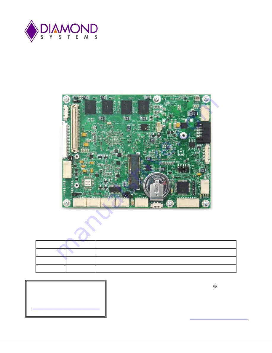
ALTAIR Single Board Computer 

COM Express Form Factor Intel Atom E-Series SBC with EMX Stackable I/O Expansion 


Revision 

Date 

Comments 

A.00 

12/6/2012 

Initial Release 

A.01 

9/3/2015 

Minor updates 

A.02 

5/01/2017 

Minor updates 


 Copyright 2015 


FOR TECHNICAL SUPPORT


Diamond Systems Corporation 


PLEASE CONTACT:


555 Ellis Street 


Mountain View, CA 94043 USA 


support@diamondsystems.com


Tel 1-650-810-2500 


Fax 1-650-810-2525 


www.diamondsystems.com


Summary of Contents for ALT1300-1G-XT

Page 1: ...on Date Comments A 00 12 6 2012 Initial Release A 01 9 3 2015 Minor updates A 02 5 01 2017 Minor updates Copyright 2015 FOR TECHNICAL SUPPORT Diamond Systems Corporation PLEASE CONTACT 555 Ellis Stree...

Page 2: ...ails 19 4 1 External Battery J2 19 4 2 CAN J3 19 4 3 SATA J4 20 4 4 Ethernet J5 20 4 5 Serial Ports J7 J8 21 4 6 USB Flashdisk J9 21 4 7 USB 0 1 J10 22 4 8 USB 2 3 J11 22 4 9 Utility Signals J12 23 4...

Page 3: ...TC Write 43 7 14 Set COM Mode 44 7 15 Get COM Mode 44 7 16 READ ANALOG DATA 45 7 17 BOARD VOLTAGES 46 7 18 PWM CONTROL 47 7 19 READ DIO CONFIG 48 7 20 CALENDAR WAKEUP 48 8 FlashDisk Modules 49 8 1 Ove...

Page 4: ...m the edge to avoid possible shorting from this type of damage However these design rules are not sufficient to prevent damage in all situations A third cause of failure is when a metal screwdriver ti...

Page 5: ...low power high performance stackable SBC Intel Atom E Series CPU at 1 6GHz 1 3GHz and 600MHz special order options 1GB or 2GB soldered DDR2 DRAM Comprehensive set of I O interfaces 4 USB 2 0 ports 1 R...

Page 6: ...corporates heatspreader and conduction cooling to the enclosure Memory 1GB or 2GB DDR2 memory soldered on board Display options LVDS flat panel interface One on board SDVO to VGA converter to a VGA co...

Page 7: ...a heatspreader attached to the Altair single board computer as a conductive cooled thermal layer However this heatspreader by itself does not constitute the complete thermal solution necessary for any...

Page 8: ...Altair User Manual Rev A 02 www diamondsystems com Page 8 2 FUNCTIONAL OVERVIEW 2 1 Block Diagram Figure 2 shows Altair s functional blocks Figure 2 Altair SBC Functional Block Diagram...

Page 9: ...er Manual Rev A 02 www diamondsystems com Page 9 2 2 Altair Dimensions Figure 3 shows the overall dimensions of the Altair SBC measured in thousandths of inches Figure 3 Altair Dimensions thousandths...

Page 10: ...SBC which features EMX stackable I O and an EMX connector The connector for the EMX expansion bus is located on the top side of the board Figure 4 Altair SBC Connector Locations LCD Backlight EMX Expa...

Page 11: ...detail in Section 4 of this document Diamond offers an optional Altair Cable Kit number C ALT KIT which provides mating cable assemblies for most of Altair s I O interface connectors Connector Functio...

Page 12: ...shows the configuration jumper groups that are located on the topside of the Altair SBC Refer to Section 5 for details on the functions and configuration options associated with each jumper group Figu...

Page 13: ...interpretation of their settings Altair s configuration jumpers are listed below Refer to Section 5 of this document for details regarding the configuration of these jumper groups Jumper Group Functi...

Page 14: ...art of Diamond s Altair Development Kit which provides everything needed to ensure rapid application development This section of the Altair User Manual covers basic hardware setup power connection sys...

Page 15: ...ent Package not shown 3 1 1 Altair Cable Kit The Altair Cable Kit number C ALT KIT provides convenient access to most of Altair s I O features The kit s cable assemblies are shown in the photo below a...

Page 16: ...dsystems com Page 16 Note On each interface cable the end of the cable connector that has a red wire going to it should be oriented toward the end of the board connector that is labeled pin 1 typicall...

Page 17: ...h the screw once the flashdisk is installed 3 2 3 Mass Storage Devices If desired connect SATA hard drives to Altair by connecting a SATA cable to SATA connector J4 and then to the SATA drive Altair c...

Page 18: ...ous other hardware and software parameters Options configurable via Setup typically include Number and type of mass storage devices Boot device priority Video display type and resolution IDA SATA seri...

Page 19: ...J2 Altair has provision for an external battery connection via J2 a two pin connector A connector and jumper are provided to disable the on board battery and enable use of an external battery instead...

Page 20: ...flush with the edge of the board so as to plug the SATA cable to an external hard drive 1 Ground 2 Transmit 3 Transmit 4 Ground 5 Receive 6 Receive 7 Ground Connector type SAMTEC 4 4 Ethernet J5 This...

Page 21: ...EY 3 4 GND KEY 3 4 GND KEY 3 4 GND RTS1 5 6 CTS1 TX1 5 6 RX1 TX1 RX1 5 6 NC SERIAL 2 NC 7 8 NC NC 7 8 NC NC 7 8 NC RX2 9 10 TX2 NC 9 10 NC NC 9 10 NC SERIAL 3 TX3 1 2 RX3 NC 1 2 NC NC 1 2 NC KEY 3 4 G...

Page 22: ...ld USB1 GND 3 4 USB0 GND USB1 Data 5 6 USB0 Data USB1 Data 7 8 USB0 Data USB1 Pwr 9 10 USB0 Pwr Connector type JST SM10B ZPDSS TF 4 8 USB 2 3 J11 This connector provides access to two of the board s f...

Page 23: ...jumper selectable default 5V 2 Power same as pin 1 3 Ground 4 Ground 5 Enable GPIO output 0 off open circuit on 6 Brightness 0 5VDC variable 0V max 5V min PWM control implemented The brightness contro...

Page 24: ...video chip 2 Ground D3 depending on video chip 3 Scan Direction High Reverse Scan Low open Normal Scan 4 LVDS Mapping High Map B Low Map A 5 Signal Ground 6 Pixel Clock 7 Pixel Clock 8 Signal Ground...

Page 25: ...26 Gnd Reserved 75 76 5V PE4C 27 28 PE1C Reserved 77 78 5V PE4C 29 30 PE1C 5VSB 79 80 LPC AD0 Gnd 31 32 Gnd 5VSB 81 82 LPC AD1 PE3C 33 34 PE2C VBat 83 84 LPC AD2 PE3C 35 36 PE2C Wake 85 86 LPC AD3 3 3...

Page 26: ...R 2 3V3 3 GND 4 PGD 5 PGC 6 NC Connector type Aptos LTY 06S2 VB 040 028 FG 4 16 PCIe MiniCard J28 The PCIe MiniCard socket provides the facility to plug in third party Mini PCIe cards such as WiFi Blu...

Page 27: ...to this connector LineOut L 1 2 LineOut R GND_AUDIO 3 4 GND_AUDIO LineIn L 5 6 LineIn R GND_AUDIO 7 8 GND_AUDIO MIC IN 9 10 GND_AUDIO Connector type JST SM10B ZPDSS TF 4 18 VGA J30 The VGA connector...

Page 28: ...Port 1 RS 422 485 mode differential termination resistor Enable or Disable JP1 2 X 2 LCD panel supply voltage 3 3V or 5V LVDS VSEL JP2 1 X 3 LCD backlight power 5V or 12V 12V provided through the inp...

Page 29: ...Backlight Power 1 2 5V default 2 3 12V 5 4 LCD Scan Direction LVDS Map Select JP5 This jumper group controls the LCD panel scan direction and frame rate control These settings depend on the LCD panel...

Page 30: ...ct Boot devices and set their priority go to the Boot menu Set the boot option priorities on this page 6 5 Chipset The chipset menu is provided to define and change the North South Bridge options such...

Page 31: ...S setup mode Use the up down arrow keys followed by carriage return to apply one of the exit actions 6 3 BIOS Screen Descriptions This section describes the screen displays for each BIOS setup area Th...

Page 32: ...tion GPIO Wake Configuration GPIO Wake Configuration Wake on GPIO0 Disabled Wake on GPIO1 Disabled Chipset North Bridge Chipset Configuration South Bridge Chipset Configuration IOH Configuration Boot...

Page 33: ...ser Password Save Exit Boot to Windows CE Save Changes and Exit Discard Changes and Exit Save Changes and Reset Discard Changes and Reset Save Options Save Changes Discard Changes Restore Defaults Sav...

Page 34: ...UT 0x09 COMMAND_DIO_READ 0x0B COMMAND_ANALOG_READ 0x0D COMMAND_CONFIG_PWM 0x0F COMMAND_WATCHDOG_SET 0x17 COMMAND_WATCHDOG_READ 0x19 COMMAND_WATCHDOG_TRIGGER 0x1B COMMAND_CALENDAR_WAKEUP 0x1D COMMAND_M...

Page 35: ...are version running on the target system If the firmware version is 2 then the message sent is 3232010 and the received message is 3232020102 7 2 Configure DIO Port Command Command Byte Length Value a...

Page 36: ...ncoded in 2 bytes of data Bit 0 to 7 for the first data byte will contain the data for DIO 0 to 7 and bit 0 and 1 of second data byte will contain the data for DIO 8 and 9 7 4 DIO Output Command Byte...

Page 37: ...bytes is the command signature the third byte is the command id the fourth byte is the length of the data buffer and the fifth byte is the data which contains the address location For example to read...

Page 38: ...d Byte Length Value and Description 0 2 MESSAGE_SIG Message signature 2 1 COMMAND_MTBF_POWER Command id 3 1 0 Indicating no data is sent Response Byte Length Value and Description 0 2 MESSAGE_SIG Mess...

Page 39: ...and Description 0 2 MESSAGE_SIG Message signature 2 1 COMMAND_RECEIVER_ACK Command id for the message 3 1 1 4 1 Return status for the command 0 Operation completed successfully 1 Some problem in the...

Page 40: ...Command id for the message 3 1 1 4 1 Return status for the command 0 Operation completed successfully 1 Some problem in the operation Comments The first three bytes contains data just like the previou...

Page 41: ...ts response which represents a timeout value depending on the value time interval chart given above 7 11 MTBF Power Data Command Byte Length Value and Description 0 2 MESSAGE_SIG Message signature 2 1...

Page 42: ...99 specifying the year s last two digits 5 1 1 12 specifying Month 1 for January 3 for March 11 for November and so on 6 1 1 31 Date 7 1 1 7 Day of week 1 for Sunday 3 for Tuesday 7 for Saturday and s...

Page 43: ...ue and Description 0 2 MESSAGE_SIG Message signature 2 1 COMMAND_RECEIVER_ACK Command id for the message 3 1 1 4 1 Return status for the command 0 Operation completed successfully 1 Some problem in th...

Page 44: ...d after the device is reset The default protocol is set as SPI communication The host windows application is uses the SPI protocol To set the protocol to RS 232 the message looks like 0x3232 0x27 0x01...

Page 45: ...ts This command retrieves the analog voltage values of channels 0 to 3 The response consists of eight bytes of data which contain the analog voltage for channels 0 to 3 in hex The data consists of the...

Page 46: ...of eight bytes of data which contain the analog voltage for channels 6 to 10 in hex The data consists of the following values 1st byte Lower byte of the voltage value of channel 6 2nd byte Higher byt...

Page 47: ...and Description 0 2 MESSAGE_SIG Message signature 2 1 COMMAND_RECEIVER_ACK Command id for the message 3 1 1 4 1 Return status for the command 0 Operation completed successfully 1 or non zero Some prob...

Page 48: ...1 of second data byte contains the data for DIO 8 and 9 7 20 CALENDAR WAKEUP Command Byte Length Value and Description 0 2 MESSAGE_SIG Message signature 2 1 COMMAND_CALENDAR_WAKEUP Command ID 3 1 6 In...

Page 49: ...no drivers It provides high speed nonvolatile mass storage in capacities of 1GB to 8GB The flashdisk mounts on connector J9 and is held in place with a spacer and screw included It includes a write pr...

Page 50: ...4 Press the flashdisk downward onto connector USB3 5 Reinstall the screw securing the flashdisk module to Altair 8 5 Power Routing A 5VDC 12VDC source can be connected to the Altair SBC power connect...

Page 51: ...depending on their needs The specifications for the thermal pad are as follows Material 3M 5590H Color Light Grey Thickness 0 5 1 0 mm Thermal Conductivity 3 0 W m K To affix the thermal pad Remove t...

Page 52: ...ed Gigabit Ethernet port on pin header with on board magnetics Mass storage o USB flashdisk mounting location supporting both sizes o 1 SATA port ALC262 Codec based High Definition Audio with Stereo L...

Reviews: