


Altair User Manual Rev A.02
www.diamondsystems.com
Page
23
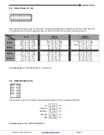
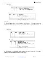
4.9 Utility Signals (J12)
This connector provides utility signals for Altair as follows.
1
USB_DEV_PWR
2
USB_DEV_D_N
3
USB_DEV_D_P
4
GND
5
SPKR
6
+5V
7
/PWRBTN
8
GND
9
/RESET
Connector type:
MOLEX, 532610971
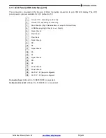
4.10 LCD Backlight (J14)
This connector provides the backlight power and control for the optional LCD panel.
Note: If needed, +12V must be provided on the input power connector.
1
Power +5V/+12V, jumper selectable, d5V
2
Power (same as pin 1)
3
Ground
4
Ground
5
Enable (GPIO output), 0 = off, open circuit = on
6
Brightness, 0-5VDC variable; 0V = max, 5V = min
(PWM control implemented)
The brightness control for the LCD backlight has a weak pull-down resistor to ensure maximum brightness when it
is not connected externally. Brightness may be controlled by a GPIO pin on the CPU or embedded microcontroller
or by pin 6 on this connector. A jumper selects the source of the brightness signal to this pin.
Connector type
:
Molex 53261-0671 or equivalent
Mating connector:
Socket: Molex 51021-0600 or equivalent
Terminals: Molex 50058 / 50079 series or equivalent


