


Altair User Manual Rev A.02
www.diamondsystems.com
Page
36
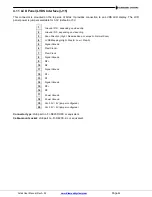
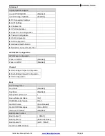
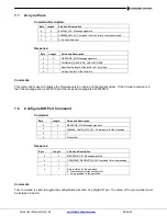
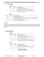
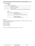
7.3
DIO Read
Command:
Byte
Length
Value and Description
0
2
MESSAGE_SIG: Message signature
2
1
COMMAND_DIO_READ:
Command id for the message
3
1
0
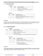
Response:
Byte
Length
Value and Description
0
2
MESSAGE_SIG: Message signature
2
1
COMMAND_RECEIVER_DIODATA: Command id for the message
3
1
2: Indicating 2 bytes data
4
2
The state of all the DIO pins from 0 to 9
Comments:
This command reads the data from all the pins starting from 0 and ending with 9. The response contains the data
for all the pins encoded in 2 bytes of data. Bit 0 to 7 for the first data byte will contain the data for DIO 0 to 7 and
bit 0 and 1 of second data byte will contain the data for DIO 8 and 9.
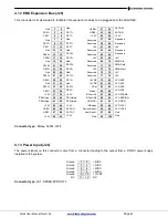
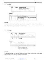
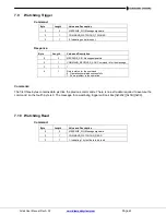
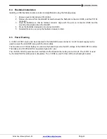
7.4
DIO Output
Command:
Byte
Length
Value and Description
0
2
MESSAGE_SIG: Message signature
2
1
COMMAND_DIO_OUTPUT
: Command id for the message
3
1
1
4
1
Pin number
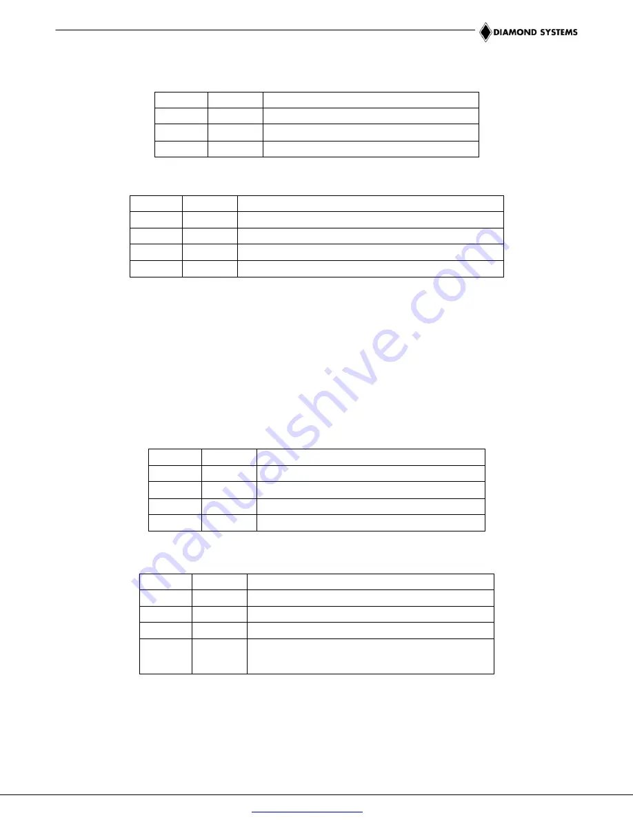
Response:
Byte
Length
Value and Description
0
2
MESSAGE_SIG: Message signature
2
1
COMMAND_RECEIVER_ACK: Command id for the message
3
1
1
4
1
Return status for the command
0: Operation completed successfully
1: Some problem in the operation
Comments:
This command toggles the current state of the selected pin from LOW to HIGH, or HIGH to LOW. The response is
an acknowledgement for the successful completion of the command.


